background image

®

C

US

IF YOU SMELL GAS

Do not try to light any appliance.

Do not touch any electrical switch;  do not use any phone in your building.

  Immediately  call  your  gas  supplier  from  a  neighbor's  phone.  Follow  the  gas 

supplier's instructions.

  If you cannot reach your gas supplier, call the fire department.

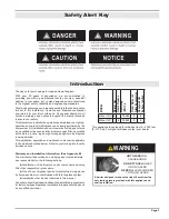
DANGER

Irritant

Cutting

Watch your step

Slippery floor

High temperatures

Glass hazard

Danger of suffocation

High voltage 

Toxic 

Flammable materials

Corrosive

Fork lift trucks 

Danger overhead crane

Explosion risk

Oxidising

Danger of death 

Biohazard

Laser Radiation

Danger of entrapment

Hot surface

General Warning

Blank

Gas bottles

Watch for 

falling objects

Electricity

Danger for cutter

Entrapment hazard

Battery hazard

Rotating parts

Low temperature

Strong magnetic field

Optical radiation

Non ionizing

 radiation

Radiation

Hazardous to the

Environment

Danger of harming 

your hands

Irritant

Cutting

Watch your step

Slippery floor

High temperatures

Glass hazard

Danger of suffocation

High voltage 

Toxic 

Flammable materials

Corrosive

Fork lift trucks 

Danger overhead crane

Explosion risk

Oxidising

Danger of death 

Biohazard

Laser Radiation

Danger of entrapment

Hot surface

General Warning

Blank

Gas bottles

Watch for 

falling objects

Electricity

Danger for cutter

Entrapment hazard

Battery hazard

Rotating parts

Irritant

Cutting

Watch your step

Slippery floor

High temperatures

Glass hazard

Danger of suffocation

High voltage 

Toxic 

Flammable materials

Corrosive

Fork lift trucks 

Danger overhead crane

Explosion risk

Oxidising

Danger of death 

Biohazard

Laser Radiation

Danger of entrapment

Hot surface

General Warning

Blank

High voltage 

Toxic 

Flammable materials

Corrosive

Fork lift trucks 

Danger overhead crane

Explosion risk

Oxidising

Danger of death 

Biohazard

Laser Radiation

Danger of entrapment

Hot surface

General Warning

Blank

April

 2014

Installer:

 Leave this manual with the appliance. 

Consumer:

 Retain this manual for future reference. 

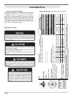
NOTICE


Glass doors on gas fireplaces are 

extremely hot

 while the fireplace is on and 

remain hot even after the fireplace has been turned off. 

CAUTIO N

This fireplace is 

equipped with a safety screen. Do not operate the fireplace without the safety 

screen. Keep children away from the fireplace at all times.  

If the information in these instructions is not followed exactly, a fire or explosion

may result causing property damage, personal injury or death. 

WARNING

Glass doors on gas fireplaces are 

extremely hot

 while the fireplace is on and 

remain hot even after the fireplace has been turned off.  Safety screens are 

available and can reduce the risks of severe burns.  Please keep children away 

from the fireplace at all times.

CAUTION

This fireplace is certified to ANSI Z21.50 / CSA 2.22 Vented Fireplace Standard as a

power assisted direct vent fireplace. This product uses outdoor air for combustion and

and exhausts combustion products outdoors.   

NOTICE

MILAN

 II

Indoor 

Gas

 Fireplace

Installation and Maintenance Manual

Summary of Contents for MILAN II

Page 1: ...ss hazard Danger of suffocation High voltage Toxic Flammable materials Corrosive Fork lift trucks Danger overhead crane Explosion risk Oxidising Danger of death Biohazard Laser Radiation Danger of entrapment Hot surface General Warning Blank High voltage Toxic Flammable materials Corrosive Fork lift trucks Danger overhead crane Explosion risk Oxidising Danger of death Biohazard Laser Radiation Dan...

Page 2: ... 15 Section 3 Finishing 32 34 Section 4 Wiring 17 18 Section 5 Installing the Gas Line 19 Section 6 Venting 20 27 Section 7 Testing the System 28 Section 8 Removing Installing the Screen and Doors 29 30 Section 9 Installing the Accessories 31 36 Operation 42 Start up Sequence 42 Maintenance 38 40 Appendix 41 42 Appendix A Warranty 41 Appendix B State of Massachusetts 42 ...

Page 3: ...tenance manual is applicable to the models described below Refer to your rating plate to verify included options Warranty and Installation Information See Appendix B The warranty will be voided by and European Home disclaims any responsibility for the following actions Modification of the fireplace and or components including Direct Vent assembly or glass doors Use of any component part not manufa...

Page 4: ...ing temperatures this appliance should be located out of traffic away from furniture and draperies Children and adults should be alerted to the hazards of the high surface temperature which could cause burns or clothing ignition Young children should be carefully supervised when they are in the same room as the appliance Clothing or other flammable materials should not be placed on or near the app...

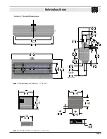
Page 5: ...7 8 303 10 255 3 1 4 82 11 1 2 292 7 1 4 186 9 5 8 244 11 7 8 303 10 255 11 1 2 292 7 1 4 186 5 3 4 148 1 3 8 34 9 5 8 244 11 7 8 303 10 255 3 1 4 82 11 1 2 292 9 5 8 244 84 11 16 2151 40 1 4 1022 73 1 8 1857 18 457 22 1 16 560 73 1 4 1861 81 1 4 2064 5 126 8 203 11 1 16 281 Gas Inlet 12 9 16 318 18 1 8 460 6 11 16 170 15 381 22 3 16 563 8 9 16 217 5 126 7 15 16 202 1 3 4 45 15 1 2 394 Light Wirin...

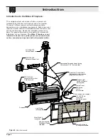
Page 6: ...l Box Cable 30 supplied standard 20 low voltage wire supplied Figure 2 Major Components Introduction Introduction to the Milan II Fireplace The complete system will require a firebox a power vent termination an electrical control panel and a vent system There are 3 different power vent terminations available depending on your installation requirements Each power vent requires a control cable to be...

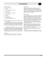
Page 7: ...You may extend these wires up to 100 in length with a wire of equal quality This fireplace is equipped with lights which need to be wired through a wall switch or dimmer circuit as shown in the schematic ON OFF control of this appliance can also be performed using an optional remote control available from your dealer Installation Sequence Unpacking and set up Framing Fireplace placement and securi...

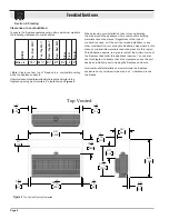
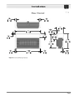
Page 8: ...16 2303 5 5 8 144 5 5 8 144 5 5 8 144 5 5 8 144 Non Combustible Zone Top Vented Rear Vented When planning your installation take into consideration the area around the appliance where combustible building materials cannot be placed Regardless of the type of construction used or if the unit is a raised installation or any other consideration or construction illustration else where in this manual co...

Page 9: ...13 16 97 2 5 8 67 2 5 8 67 90 11 16 2303 5 5 8 144 5 5 8 144 90 11 16 2303 2 5 8 67 2 5 8 67 1 1 2 38 15 1 4 388 96 2438 55 1 2 1410 3 13 16 97 20 509 52 1 2 1334 26 660 4 1 16 103 Rear Vented Figure 3a Rear Vented Framing Clearances ...

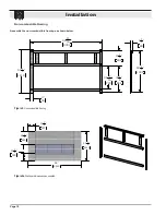
Page 10: ...ming Assemble the non combustible framing as shown below 90 11 16 2303 55 1 2 1410 3 76 33 1 4 844 19 1 4 490 28 7 16 723 52 1 2 1334 3 1 2 89 90 11 16 2303 55 1 2 1410 1 3 4 45 33 1 4 844 19 1 4 490 3 76 Exploded View Figure 4 Non combustible framing Figure 4a Wall board dimensions as supplied ...

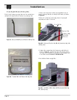
Page 11: ...ten the cover with included hardware as shown in Figure 5a 4 Install the collars 5 and 8 to the rear vent outlet using the included hardware as shown in Figure 5a 5 Proceed to Section 3 1 2 Converting Pressure Sensing Tube and Air Baffle 5 Inner Flue Collar 8 Outer Flue Collar 8 Flue Cover Plate 5 Flue Cover Plate with gasket with gasket with gasket with gasket 8 Flue Cover Plate 5 Flue Cover Plat...

Page 12: ...sition the tube in the center of the 5 inch pipe Hand tighten the compression nut and tighten half a turn with a wrench DO NOT OVERTIGHTEN Top of Firebox Top of Firebox Pressure Tube Firebox ceiling with baffle removed The Top Vent pressure sensing tube must be removed and replaced with supplied Rear Vent pressure sensing tube Figure 6 Factory installed Top Vent Pressure Sensing Tube Figure 6a Sup...

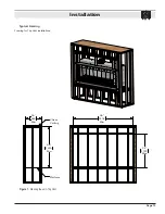
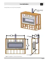
Page 13: ...Page 13 Installation Framing for Top Vent installations 66 1676 Min 26 660 Min Platform Chase Ceiling 96 2438 Min 54 1372 Max Chase Constuction TV Typical Framing Figure 7 Framing the unit Top Vent ...

Page 14: ...Page 14 Installation Framing for Rear Vent installations 55 1 2 1410 Min 26 660 Min Platform Chase Ceiling 96 2438 Min 54 1372 Max Chase Constuction RV Figure 7a Framing the unit Rear Vent ...

Page 15: ... Vertical Vent Run installations Firestop required when penetrating ceilings 96 2438 Min 52 1 2 1334 Max 36 1 2 927 Min Chase Ceiling Platform Chase Constuction Rear Vent with Vertical Vent Figure 7b Framing the unit Rear Vent Vertical Vent Run ...

Page 16: ...ent Temperaturesoverthemantelwillriseabovenormal room temperature and walls above fireplace may be hot to touch We recommend careful consideration be given to the effects of elevated mantel temperatures which may be in excess of product design for example candles plastic or pictures This can cause melting deformation discolouration or premature failure of T V and radio components Side wall clearan...

Page 17: ...rvice may be made easily Conduit Wiring clearances Connect the power vent harness as outlined in the previous section Ensure that the proper clearances are maintained for the wiring and conduit When installing the wiring it must never run above the vent run and it must be at least 1 clear of all venting 1 Clearance Wire Note If any of the original wire supplied with the appliance is replaced it mu...

Page 18: ... Black Blk Wht Wht Blk Blue Red Brown NC Heat Sensor NO Flue Gas Switch ELECTRICAL CONTROL BOX R3 Gas Valve Wall Switch Fuse 115 Volts 60Hz 5A Post Purge Timer Pre Purge Timer Honeywell Q3450 Pilot Assembly Pilot Electrical Harness Connector Honeywell Gas Control SV9501M Gas Control Connector Green Black White Switch or Dimmer Not Supplied Power for Lights 115VAC 700W FIREPLACE CONTROLS Red Tube C...

Page 19: ...s have a provision to remove a 1 8 MPT plug and to be fitted with a hose barb A service shut off valve is required in an accessible location to isolate the appliance Only install gas shut off valves approved for use by the state province or other governing body in which the fireplace is being installed GAS CONNECTION See Figure 15 below for location of gas line access Flexible gas connectors must ...

Page 20: ...d horizontal runs can be calculated in the same manner Flexible venting does not flow quite as well as rigid pipe so a factor needs to be applied making the total allowable vent run shorter than rigid pipe Not for rigid elbows used in between flex sections Venting Calculation Rigid Vent Flex Venting Maximum Vent Run Rigid 80 total length 60 total length 90 degree elbow subtract 10 each subtract 5 ...

Page 21: ...ide for the PVVEX58 300 PVVEX58 300 Vertical Power Vent Detail Front View Not Acceptable Side View Front View Top View 24 24 Wall Wall 18 40 1016 mm 18 Min Wall 24 610 mm 610 mm 610 mm 457 mm Figure 16 PVVEX58 300 Figure 16a PVVEX58 300 clearances Figure 16b PVVEX58 300 restrictions ...

Page 22: ... cm J Clearance to nonmechanical air supply inlet to building or the combustion air inlet to any other appliance 6in 15 cm for appliances 10 000 Btuh 3 kW 12 in 30 cm for appliances 10 000 Btuh 3 kW and 100 000 Btuh 30 kW 36 in 91 cm for appliances 100 000 Btuh 30 kW Canadian Installations US Installations 1 2 6in 15 cm for appliances 10 000 Btuh 3 kW 9 in 23 cm for appliances 10 000 Btuh 3 kW and...

Page 23: ...ctionsonthisterminationseeinstructionguide for the PVHEX58 300 PVHEX58 300 Horizontal Power Vent Detail Eaves Overhang Wall 14 355mm 32 813mm 16 6 6 Side View 152mm 152mm 406mm Figure 17 PVHEX58 300 Figure 17a PVHEX58 300 Termination Clearances ...

Page 24: ... service regulator vent outlet 3 ft 91 cm J Clearance to nonmechanical air supply inlet to building or the combustion air inlet to any other appliance 6in 15 cm for appliances 10 000 Btuh 3 kW 12 in 30 cm for appliances 10 000 Btuh 3 kW and 100 000 Btuh 30 kW 36 in 91 cm for appliances 100 000 Btuh 30 kW Canadian Installations US Installations 1 2 6in 15 cm for appliances 10 000 Btuh 3 kW 9 in 23 ...

Page 25: ...0 Horizontal Power Vent Detail Front View Eaves Overhang Wall 24 610mm 24 15 15 24 610mm 152mm 152mm 622mm Forinstallationinstructionsonthisterminationseeinstructionguide for the PVHFL58 300 Figure 18 PVHFL58 300 Figure 18a PVHFL58 300 Termination Clearances ...

Page 26: ...ce to service regulator vent outlet 3 ft 91 cm J Clearance to nonmechanical air supply inlet to building or the combustion air inlet to any other appliance 6in 15 cm for appliances 10 000 Btuh 3 kW 12 in 30 cm for appliances 10 000 Btuh 3 kW and 100 000 Btuh 30 kW 36 in 91 cm for appliances 100 000 Btuh 30 kW Canadian Installations US Installations 1 2 6in 15 cm for appliances 10 000 Btuh 3 kW 9 i...

Page 27: ...ow PEL 90FF f f 90º Elbow PEL 90FM f m 90º Elbow PEL 45FM f m 45º Elbow E Support Ring Plate RSPXT 8 F Firestop FS 8 G Heat Shield RHS101 Connection and installation of the vent components must adhere to the following Theuseofaflexsectionforthefinalpipe connection at the fireplace is recommended It offers greater flexibility of installation and absorption of movement Firestops must be installed as...

Page 28: ...or will be illuminated Install the inner window light tray glass and outer window see appropriate sections Place the appliance in operation See the lighting instructions on page 37 Once the appliance is operational confirm the manifold pressure and supply pressure are within the specified limits see section 5 Turn lights on and confirm all lights are working The Milan II Control and Power Vent Sys...

Page 29: ...ows Figure 20 Removing the screen There are two tabs located at either end of the screen bottom By grasping these tabs lift the screen upward into the upper track Once the screen has cleared the bottom track pull the bottom of the screen away and downwards from the unit to remove the screen from the upper track Figure 20a Step 1 Grasp the trim on either side of the door with the tips of your finge...

Page 30: ...he top edge of the glass panel is fully removed from the upper outer track Then tilt and lift away cautiously from the fireplace Store in a safe location Step 5 Attach suction cups on the inner glass door Remove the four inner glass retainers at the top of the glass see figure for glass retainer placement Caution keep at least one hand on suction cup attached to the inner glass when removing the l...

Page 31: ... tray Figure 23b Completed firestone installation Optional Speckled Stones The Milan II has the option of installing the Speckled Stones which mimic real stone These may be spaced evenly across the burner and or light tray Section 9 Installing Accessories Figure 23a Do not place any firestones on top of the pilot cover Do not operate this fireplace without the glass doors or with abroken glass doo...

Page 32: ...h log in the location shown in figure 24a Use the porcelain panel joints as reference The logs should be behind the burner ports and leaning against the porcelain panel The log placed on the right should be orientated 180 compared to the left log Pilot Step 2 Identify logs in kit LGS58 LGS58 1 2 3 4 5 6 Figure 24d Place Log 1 behind the burner port next to the right log of LGS57 Place log 2 on top...

Page 33: ...ght log from LGS57 Cross log 4 over the ports Place log 2 on the right end of the right log from LGS57 See Figure 24l Figure 24L 4 2 Step5 FromLGS58 Placelog5ontopoftheendoftherightlogfrom LGS57 and cross the burner to log 3 see figure 24m Place log 6 on top of the end of log 2 and cross the burner to log 3 see figure 24n Figure 24m 5 6 3 Ports Figure 24 n Figure 24o Step 6 Place log 6 from LGS58 ...

Page 34: ...Page 34 Installation Step 7 Place the logs from LGS59 in any configuration you find pleasingovertopofthelighttray Besuretoinstalltheinnerglassfirst Figure 24r LGS59 1 2 3 4 5 6 Figure 24q ...

Page 35: ...57 Both logs are identical Place each log in the location shown in figure 25a Use the porcelain panel joints as reference The logs should be behind the burner ports and leaning against the porcelain panel Figure 25b The log placed on the right should be oriented 180 compared to the left log Step 2 Identify logs in kit LGS58 LGS58 1 2 3 4 5 6 Place Log 5 on the left end of the left log from LGS57 K...

Page 36: ... end of the ports DO NO place the log over the ports Figure 25m Figure 25n Step 6 From LGS59 place log 3 in front of the ports near the middle of the burner in front of the right log from LGS57 Place log 3 on top of log 3 see figure 25o 2 3 Figure 25o From LGS59 place log 5 in front of the ports near the middle of the burner infront of the left from from LGS57 Place log 6 from LGS58 on top of log ...

Page 37: ...ad the safety information above on this label 2 Turn the wall switch to ON or activate the remote control if so equipped 3 The heat sensor LED indicator and wall switch LED indicator will light up and the power vent will start Within 30 seconds the flue gas LED indicator will be illuminated 4 The ignitor will start to glow after the 60 second pre purge period 5 If the pilot does not light the gas ...

Page 38: ...l compartment burner and firebox free from dust and lint Do not use ammonia based or abrasive cleaners on the glass they will permanently etch the surface Use an approved gas fireplace glass cleaner NOTICE Section 10 Cleaning and Maintenance Procedure for Checking The Flue Gas Switch and Thermal Switch 1 Remove the safety screen and outer glass see appropriate sections 2 Disconnectthepowerventharn...

Page 39: ...ssfully removed proceed with figures 28 28b Note Always wear gloves when handling the fireplace light bulbs or glass panels Figure 28 Figure 28a Figure 28b Step 1 Remove remove any decorative media and up lighting glass from the light kit tray Step 2 To remove a light bulb pull the light bulb away from the light bulb connector and lift the light bulb up and out Step 3 Rotate the newly replaced lig...

Page 40: ...e gas connection cover Figure 29e After removing the appropriate fasteners remove the burner assembly Figure 29d Disconnect the flexible gas connection line Figure 29f Remove the valve cover to gain access to the valves Step 1 Step 2 Remove firestones Step 3 Step 4 Lift one end of the rail up above the firebox ceiling baffle Pull the other end out the front of the fireplace Step 5 Step 6 Step 7 Fi...

Page 41: ...ty Some states do not allow limitation on how long an implied warranty lasts so the above may not apply to you Investigation Of Claims Against Warranty The Company reserves the right to investigate any and all claims against this Warranty and to decide upon method of settlement The Company Is Not Responsible For Work Done Without Written Consent The Company shall in no event be responsible for any...

Page 42: ...ve grade directly in line with the exhaust vent terminal for the horizontally vented gas fueled heating appliance or equipment The sign shall read in print size no less than one half 1 2 inch in size GAS VENT DIRECTLY BELOW KEEP CLEAR OF ALL OBSTRUCTIONS 4 INSPECTION The state or local gas inspector of the side wall horizontally vented gas fueled equipment shall not approve the installation unless...

Page 43: ...Page 43 Notes ...
Page 44: ...EUROPEAN HOME a division of Europa Ja Inc 376 Washington St Suite 203 Malden MA 02148 tel 781 324 8383 fax 781 324 8384 www europeanhome com ...

Reviews: