Page 8
Installation
Section 2: Framing
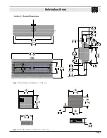
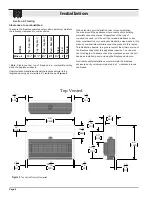
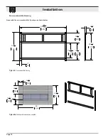
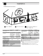
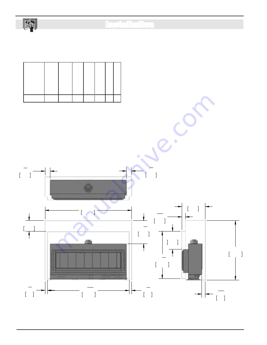
Figure 3.
Top Vented Framing Clearances
Clearances to combustibles:
To ensure the fireplace operates safely, all models must maintain
the following clearances to combustibles:
Milan II
15
¼
" 25
¾
" 4⅜" 4⅜" 5⅝" 0 2"
MODEL
Top - Rear V
ent
†
Rear - T
op V
ent
Top - T
op V
ent
†
†
Note:
Clearance from top of fireplace to a combustible ceiling
within the fireplace enclosure.
Unprotected combustible walls which are perpendicular to the
fireplace opening must maintain 6" clearance, see
F
igure 9
.
Rear - Rear V
ent
Sides
Floor
Mantel
26"
660
66"
1676
4 1
16 "
103
52 12 "
1334
3 13
16 "
97
20"
509
2 58 "
67
2 58 "
67
12"
305
96"
2438
25 34 "
655
90 11
16 "
2303
5 58 "
144
5 58 "
144
5 58 "
144
5 58 "
144
90 11
16 "
2303
2 58 "
67
2 58 "
67
1 12 "
38
15 14 "
388
96"
2438
55 12 "
1410
3 13
16 "
97
20"
509
52 12 "
1334
26"
660
4 1
16 "
103
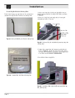
Non-Combustible Zone
Top Vented
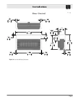
Rear Vented
When planning your installation, take into consideration
the area around the appliance where combustible building
materials cannot be placed. Regardless of the type of
construction used, or if the unit is a raised installation or any
other consideration or construction illustration else where in this
manual, combustible materials cannot be placed in this region.
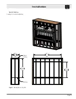
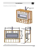
This illustration depicts to a greater extent the minimum size of
the fireplace chase that this appliance requires. You can also
use this diagram to double check the clearances once the unit
has been installed, prior to closing the fireplace enclosure.
Non-combustible installations must maintain the fireplace
enclosure cavity volume minimum and a 1" clearance around
the firebox.
Summary of Contents for MILAN II
Page 43: ...Page 43 Notes ...


