background image

1

WARNING: If the information in these 

instructions is not followed exactly, a fire 

or explosion may result causing property 

damage, personal injury or loss of life.

WHAT TO DO IF YOU SMELL GAS

•  Do not try to light any appliance.
•  Do not touch any electrical switch; do 

not use any phone in your building.

•  Immediately call your gas supplier 

from a neighbor’s phone. Follow the 

gas  supplier’s instructions.

•  If you cannot reach your gas supplier, 

call the fire department.

Do not store or use gasoline or other 

flammable vapors and liquids in the vicinity 

of this or any other appliance. Installation 

and service must be performed by a qualified 

installer, service agency or the gas supplier.

Ce manual est disponsible en Français sur de-

mande.

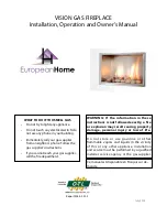
VISION GAS FIREPLACE

Installation, Operation and Owner’s Manual

Report #284-F-01-5

July 2014

Summary of Contents for VISION GAS FIREPLACE

Page 1: ...y call your gas supplier from a neighbor s phone Follow the gas supplier s instructions If you cannot reach your gas supplier call the fire department Do not store or use gasoline or other flammable vapors and liquids in the vicinity of this or any other appliance Installation and service must be performed by a qualified installer service agency or the gas supplier Ce manual est disponsible en Fra...

Page 2: ...Supply 15 Framing 18 Installing the Fireplace 19 Gas Supply 19 Venting 20 Facing 21 Installing the Burner Module 23 Panel Installation 27 Stone Configuration 28 Surrounds 30 Lighting Instructions 31 Maintenance 34 VBM Troubleshooting 36 24VBM Troubleshooting 38 Parts List 39 Warranty 40 Third Party Connections Appendix A Power Venting the Vision Gas Fireplace Appendix B ...

Page 3: ...a qualified service technician to inspect the appliance and to replace any part of the control system and any gas control which has been under water 11 Due to high temperatures the appliance should be located out of traffic and away from furniture and drap eries 12 Children and adults should be alerted to the hazards of high surface temperatures and should stay away to avoid burns or clothing igni...

Page 4: ...t de l entretien des commandes étiquetez tous les fils avant de les débrancher Des erreurs de câblage peuvent entraîner un functionnement inadéquat et dangereux S assurer que l appariel fonctionne adéquatement une fois l entretien terminé Cet appareil doit être ustilisé uniquement avec les types de gaz indiqués sur la plaque signalétique Cet appareil ne peut être converti a d autres gaz AVERTISSEM...

Page 5: ...ted gas fueled equipment is installed in a crawl space or an attic the hard wired carbon monoxide detector with alarm and battery back up may be installed on the next adjacent floor level b In the event that the requirements of this subdivision can not be met at the time of completion of installation the owner shall have a period of thirty 30 days to comply with the aboverequirements provided howe...

Page 6: ...stem d MANUFACTURERREQUIREMENTS GASEQUIPMENTVENTINGSYSTEMNOTPROVIDED Whenthe manufacturerofaProductApprovedsidewallhorizontallyventedgasfueledequipmentdoesnotprovide the parts for venting the flue gases but identifies special venting systems the following requirements shall be satisfied by the manufacturer 1 The referenced special venting system instructions shall be included with the appliance or...

Page 7: ... MAINTENANCE section for details NOTE You should have the following tools and supplies Thank you for purchasing the Vision Gas Fireplace by European Home Please read this manual thoroughly before beginning the installation of your Vision Gas Fireplace It has information which is important for safe trouble free installation and operation You have ordered your Vision Gas Fireplace with one of two av...

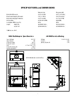
Page 8: ...DMS Canadian Efficiency P 4 32 39 Input High Fire 42 000 BTU hr 43 500 BTU hr Low Fire 27 000 BTU hr 27 000 BTU hr VBM burner ONLY All dimensions are in inches VBM Wall Adapter Specifications Input Voltage 120V AC Input Power 9 W Output Voltage 6V DC Output Current 500 mA Size 3 1 H x 2 W x 1 7 D Output Cord Length 6 Feet Agency Approvals UL CSA 24VBM Electrical Rating Voltage 120V AC 60 Hz Curren...

Page 9: ...or maintenance can cause injury or property damage Refer to the owner s information manual provided with this appliance For assistance or additional information consult a qualified installer service agency or the gas supplier AVERTISSEMENT Une installation un réglage une modification une réparation ou un entretien mal effectué puet causer des dommages matériels ou des blessures Voir la notice de l...

Page 10: ...10 Vision Gas Fireplace Listing Label for 24VBM Burner ...

Page 11: ...Fireplace with a 24VBM burner is powered by a 24V AC transformer included which must be wired to a 120V AC branch circuit The 24V AC side of the transformer is switched with a customer supplied 24V AC rated switch Label all wires prior to disconnection when servicing controls Wiring errors can cause improper and dangerous operation This appliance must be electrically grounded in accordance with lo...

Page 12: ...aded area shown in Figure 1 Combustible materials must not be located inside the areas defined by the standoffs in Figure 2 Also see Figure 7 in the FRAMING section Mantels may be installed provided the top of the mantel is not higher than the combustible limit If a mantel is required above the combustible limit then non combustible facing must be used up to the top of the mantel Combustible woode...

Page 13: ...NON combustible wall facing Vision Gas Fireplace opening Top of Vision Gas Fireplace opening Combustible mantels may be placed no closer to the Vision Gas Fireplace opening than the distances shown in the Figure 3a side view above Figure 3a ...

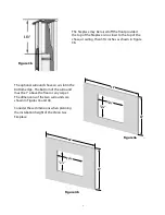
Page 14: ...n in Figure 3b 351 2 The optional surrounds have an air slot in the bottom edge The bottom of the surround must be 1 above the floor or any carpet The dimensions of the two surrounds are shown in Figures 4a and 4b Consider these dimensions when planning the installation height of the Vision Gas Fireplace 261 4 Figure 4b 167 8 34 48 261 4 167 8 28 54 Figure 4a ...

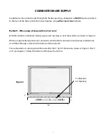
Page 15: ...und With this method a minimum twenty square inch opening is cut in the wall face as shown in Figure 5 When an optional European Home surround is mounted this combustion air opening is hidden and air will flow through a cutout in the bottom of the surround This combustion air opening should be cut within the 3 by 30 dimensions shown in Figure 5 This 3 x 30 area begins 1 below the bottom of the low...

Page 16: ...ll cases the opening must be at the burner level Allow air to flow freely between your opening and the fireplace cabinet The opening and the cabinet do not have to be connected by ducting but air must be able to flow freely between the opening and the cabinet Any materials such as insulation which will impede this free flow of air must be removed If a combustion air supply is not implemented corre...

Page 17: ...llation of an outside air kit which is not provided The final determination of the suitability of any particular kit must be made by the installer If an outside air supply is desired it should be added to the room in which the Vision Gas Fireplace is installed not to the chase enclosing the Vision Gas Fireplace If outside air is introduced into the chase competing air pressures could compromise th...

Page 18: ...ed around the Vision Gas Fireplace opening it must be 2x4 framing ONLY Figure 7 shows the minimum chase opening of 33 wide 461 4 high and 16 deep Figures 8 9a and 9b show typical framing construction Figure 9a Figure 8 Figure 9b Figure 7 ...

Page 19: ...g system during any pressure testing of that system at test pressures in excess of psi 3 5 kPa The Vision must be isolated from the gas supply piping system by closing the main control valve during any pressure testing of the gas supply system at test pressures equal to or less than psi 3 5 kPa Note This product must be installed by a licensed plumber or gasfitter when installed within the Commonw...

Page 20: ...ned The first piece of venting is a draft hood connector which is available through your vent pipe supplier Trim the aluminum extension of the connector to 1 inch from the outer steel pipe as shown in Figure 12 Place the connector on the flue outlet so that the aluminum piece goes inside the flue outlet and the steel piece goes outside Screw the two anchoring tabs to the draft hood connector as sh...

Page 21: ...l must be used in the gray area shown in Figure 14 Conventional drywall may be used OUTSIDE of this area The joints can be finished with conventional joint compound and fiberglass mesh joint tape See Figure 15 below Figure 15 Figure 14 381 2 49 Non combustible material such as stone or tile may be used as a facing See Figure 16 below Figure 16 ...

Page 22: ...rted by their manufactur ers to be BOTH non combustible in accordance with the ASTM E136 standard AND approved for use around fireplaces Product Non combustible Manufacturer Approved James Hardie Building Products HardieBacker 1 4 Cement Board YES YES James Hardie Building Products HardieBacker 500 Cement Board YES YES Promat PROMATECT L Insulating Boards YES YES Skamol Skamotec 225 YES YES U S Ar...

Page 23: ...ions each end of the blocked flue sensor wiring harness must be connected to the VBM burner module 24VBM Burner Module This burner module is wired to a 120V AC branch circuit via the 24VBM wiring assembly The blocked flue sensor wiring harness must be re terminated for connection to the 24VBM burner If the 24VBM Burner Module will be used in a power vented induced draft installation please see App...

Page 24: ...Fasten with the two nuts and washers provided See Figure 18 Figure 18 Tighten Here Tighten Here Connect AC wall adapter here VBM burner only Figure 19 VBM Burner ONLY Connect the blocked flue sensor wires red and violet as shown in Figure 19 Connect the wall adapter to the receiver as shown in Figure 18 and plug the wall adapter into a 120V AC receptacle Violet Red ...

Page 25: ...tor of the wiring assembly 3 Connect the violet wire female connector of the blocked flue sensor harness onto the TR terminal of the control module 4 Connect the yellow wire to the TH terminal of the control module 5 Wire the 24V AC transformer to a 120V AC branch circuit observing all applicable codes 6 Connect the red transformer lead female to 24V and the green transformer lead male to 24V 7 Co...

Page 26: ... the fittings to check for gas leaks Never use a flame to test for leaks If you are installing a propane burner check that the air shutter see Figure 22 is in the open position Replace the burner in the burner module Ensure that the burner inlet tube is in the shutter box and tighten the screw shown in Figure 17 Air shutter shown in the open position for propane only Figure 21 Figure 22 ...

Page 27: ...arth Panel Side Panel Clip Remove the rear panel clips and place the rear panel at the back of the fireplace Reinstall the rear panel clips Place the side panels on each side of the fireplace Slide the side panels to the rear and install the panel clips to retain the side panels Place the hearth panel in the fireplace with the small notch to the front over the pilot as shown in Figure 24 Figure 23...

Page 28: ...n Slight differences in the placements are acceptable When using the stones and embers begin by placing one layer of the embers evenly over the entire burner top as shown in Figure 25 Sort your stones by size into sixteen small three medium and four large Place a row of six small stones along the rear edge of the burner as shown in Figure 26 Figure 25 S S S S S S Figure 26 ...

Page 29: ...nd three small stones on the burner as shown in Figure 27 Then place two medium and four small stones along the front edge of the burner as shown in Figure 28 Figure 27 S S S S S S S S S L L Figure 28 L L S S S S S S S S S S S S M M S ...

Page 30: ...l surrounds available for the Vision Gas Fireplace Ensure that the surround model is correct for the fireplace installation so the combustion air is not blocked Attach the surround mounting brackets per the instructions included with the surround and hang the surround on the brackets Figure 29 S M L S S L L L M M S S S S S S S S S S S S S ...

Page 31: ...n Home Technical Support B BEFORE LIGHTING smell all around the appliance area for gas Be sure to smell next to the floor because some gas is heavier than air and will settle on the floor WHAT TO DO IF YOU SMELL GAS Do not try to light any appliance Do not touch any electric switch do not use any phone in your building Immediately call your gas supplier from a neighbor s phone Follow the gas suppl...

Page 32: ...nce you hear a beeping noise This acoustic signal tells you that the start sequence has begun Further short signals will continue until main gas flows and the burner is lit If the pilot or burner does not light go back to Step 3 above 6 Use the up and down arrows to adjust the flame height LIGHTING THE FIRE Push the OFF button on the remote control to turn the appliance off TO TURN OFF THE APPLIAN...

Page 33: ... out any gas Then smell for gas including near the floor If you smell gas STOP Follow B in the Safety Information on page 31 If you don t smell gas go to the next step 5 Set the Flame Switch to ON The system will spark to light the pilot flame When the pilot flame is lit the main burner will light 6 If the pilot flame does not light go back to Step 3 above Set the Flame Switch to OFF to turn off t...

Page 34: ...to the STONE CONFIGURATION section of this manual Inspecting the Venting An inspection of the vent pipe and termination should be made as part of the annual service appointment The venting must have no blockage and be in good repair The vent manufacturer s instructions may provide specific details on vent inspection Any vent sections that are disassembled must be reassembled and sealed as required...

Page 35: ...tructions With all parts of the fireplace at room temperature remove the stones Lift out the bottom liner panel from the fireplace Remove the two screws and the valve heat shield as shown in Figure 31 to access the control module on the left side Replace the old batteries with four high quality AA alkaline batteries Re install the heat shield and bottom liner panel Figure 31 ...

Page 36: ...ce the transmitter and reprogram code as above 1 Secure wire 2 Replace receiver and reprogram code as above 3 Straighten pins on 8 wire connector 4 Replace valve 1 Purge the line or start ignition several times 2 Check spark gap check wiring connec tion Check for spark in location along cable 3 Replace valve Do not over tighten the thermocouple POSSIBLE CAUSE 1 Receiver must learn new code 2 Dead ...

Page 37: ... the spade connector closest to the thermocouple and thermocouple tube itself The reading should be 21 30 mV 2 Replace thermocouple 3 Confirm regulator pressure and sizing Replace if necessary 4 Replace valve Do not over tighten the thermocouple 1 Replace batteries 1 Turn manual override knob to ON position see figure 4 2 Turn flame to high fire by pressing up button on remote control 3 Confirm re...

Page 38: ...ensor is not shorted to ground replace the control module A flashing light indicates the problem is most likely in the external components or wiring See LED Code Table below Proceed as follows Visual checks 1 After the purge delay if applicable the pilot valve opens and the ignition spark starts 2 The pilot burner flame will light 3 The ignition spark stops and the main valve opens 4 The main burn...

Page 39: ...e Kit VPK 01 Pilot Assembly VPA 01 Vent Safety Switch VVSS 01 Stainless Liner Kit VSLK 01 Small Stainless Surround VSSS 01 Large Stainless Surround VLSS 01 Small Stone Surround VSST 01 Large Stone Surround VLST 01 For replacement parts and customer service contact EUROPEAN HOME a division of Europa Ja Inc 376 Washington St Suite 203 Malden MA 02148 tel 781 324 8383 fax 781 324 8384 www europeanhom...

Page 40: ... PRODUCT INSTALLATION RECORD Installer Please complete this form Customer Please retain this information Purchased From Date of Purchase Installed By Date of Installation Fireplace Serial Number Fuel Type ...

Page 41: ...ing assembly Connect the violet wire female connector of the blocked flue sensor harness onto the TR terminal of the control module Connect the yellow wire to the TH terminal of the control module See Figure A 2 Step 3 Transformer Connection Wire the 24V AC transformer to a 120V AC branch circuit observing all applicable codes Connect the red transformer lead female to the wire marked 24V and the ...

Page 42: ...42 Figure A 1 Sensor Harness Red Sensor Wire Cut strip and crimp here to blocked flue sensor Violet Sensor Wire Connect to TR Figure A 2 Control Module Connections T H T R Red Sensor Wire connects here ...

Page 43: ...43 Figure A 3 Transformer Connections ...

Page 44: ...h European Home The RS 009 is an externally mounted fan which may be mounted on a wall or roof the RSIF 146 is an internally mounted fan which may be used with a wall or roof termination but which MUST be mounted indoors The Vision venting requirement is reduced from 8 diameter Type B vent to 6 diameter Type B vent ONLY WHEN USING THE ENERVEX RS 009 or RSIF 146 POWER VENT The RS 009 may be used wi...

Page 45: ...C L1 N FLAME SWITCH LO TEMP SNAP SWITCH TH TR Burner Control Module 14 AWG stranded Field Wiring 14 AWG Romex LEGEND 24V AC TRANSFORMER Wiring Schematic for 24VBM xx 01 Burner and Enervex ADC100 Controller DISCONNECT by others FAN OUT 24VDC AUX 1 IN ADC100 AC IN ...

Page 46: ...When in doubt follow the ADC100 installation manual Ensure that make up air is available in the room in which the Vision Gas fireplace is installed Your project HVAC engineer should be consulted prior to this installation INSTALLATION Install a LO TEMP SNAP SWITCH in place of the standard Vision Gas Fireplace snap switch Ensure that all necessary jumpers are in place on the ADC100 The stack probe ...

Page 47: ...control circuit and turning off the Vision Gas Fireplace If proper draft is not maintained because of wind pressure or other pressure disturbance the ADC100 will gradually increase the speed of the fan until proper draft is achieved If the increased speed does not provide sufficient draft the ADC100 will not allow the Vision Gas Fireplace to light PARTS LIST Enervex RSxx Power Vent p n PV VM PV RS...

Page 48: ...48 rev 141113 EUROPEAN HOME a division of Europa Ja Inc 376 Washington Street Suite 203 Malden MA 02148 www europeanhome com ...

Reviews: