19
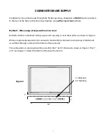
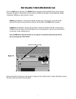
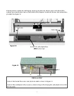
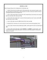
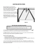
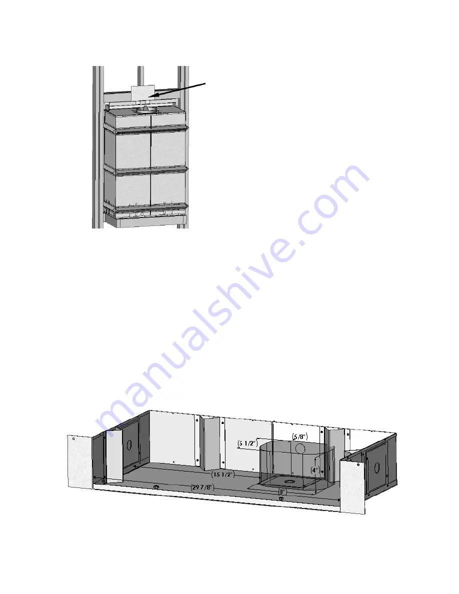
Route the gas supply into the fireplace cabinet. The gas supply line must terminate with a male ½”
NPT pipe thread in the shaded area in Figure 11. The gas supply line can be routed through the knock
outs provided on the back, sides and bottom of the fireplace. The gas supply piping should have a
separate gas shutoff valve and a ½” NPT plugged tapping up stream of the valve for reading pressure.
The Vision and its main control valve must be disconnected from the gas supply piping system
during any pressure testing of that system at test pressures in excess of ½ psi (3.5 kPa). The Vision
must be isolated from the gas supply piping system by closing the main control valve during any
pressure testing of the gas supply system at test pressures equal to or less than ½ psi (3.5 kPa).
Note: This product must be installed by a licensed plumber or gasfitter when installed within
the Commonwealth of Massachusetts.
GAS SUPPLY
INSTALLING THE FIREPLACE
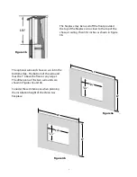
After the framing has been completed, the
fireplace can be installed. Place the header
heat shield extension on the center of
the header heat shield flange as shown in
Figure 10.
Figure 10
Figure 11
Header heat
shield flange

