23
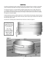
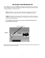
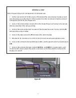
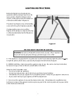
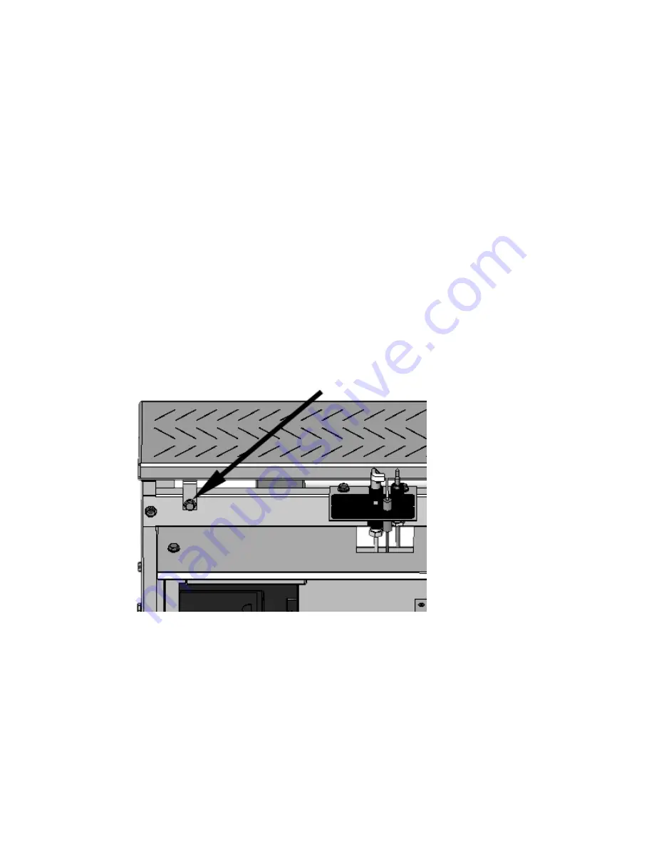
Burner Locking Screw
Figure 17
INSTALLING THE BURNER MODULE
Either a
VBM
burner module or a
24VBM
burner module may be installed into your Vision Gas
Fireplace. Except for the electrical connections, both burner modules install identically. Where
installation differences exist they are noted.
VBM
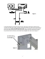
Burner Module – This burner module requires two connections; each end of the
blocked flue sensor wiring harness must be connected to the
VBM
burner module.
24VBM
Burner Module – This burner module is wired to a 120V AC branch circuit via the
24VBM wiring assembly. The blocked flue sensor wiring harness must be re-terminated for
connection to the 24VBM burner.
If the 24VBM Burner Module will be used in a power vented (induced draft) installation
please see Appendix A for details.
Remove the burner locking screw (shown in Figure 17) from the burner module. Slide the burner to
the left and remove it from the module.


