25
24VBM Burner ONLY
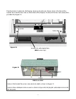
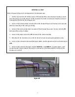
Refer to Figure 20, Figure 21 and Appendix A for detailed views.
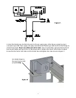
1. Cut the ring terminal off of the red wire of the blocked flue sensor harness leaving as much
wire remaining as possible. Strip 1/4” of the insulation from the cut end and crimp the enclosed
male push terminal onto this stripped end.
2. Connect the red wire (male connector) from the blocked flue sensor harness to the red wire
(female connector) of the wiring assembly.
3. Connect the violet wire (female connector) of the blocked flue sensor harness onto the
TR
terminal of the control module.
4. Connect the yellow wire to the
TH
terminal of the control module.
5. Wire the 24V AC transformer to a 120V AC branch circuit observing all applicable codes.
6. Connect the red transformer lead (female) to
24V +
and the green transformer lead (male) to
24V -
7. Connect the red and white leads (marked
and
SWITCH -
respectively) to a 24V
AC rated switch (not provided.) This switch is referred to as the Flame Switch and it turns the
Fireplace on and off.
Figure 20
TR
TH
Control Module


