38
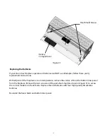
Since the LED on the control module is hard to see after the Fireplace has been installed, the following
assumes that the 24VBM Burner Assembly has been safely connected to a test bench and that all
appropriate safety precautions are being observed.
For proper operation, the control module must be electrically connected to the gas valve and all the
ignition wiring connectors plugged in.
The LED light on the control module provides a self-diagnosis indication. If the red LED is off
continuously, the fault is likely to be internal to the module. To make sure, interrupt the line or 24
volt power for 10 seconds, check program key installation and then restore. If the internal fault is
indicated again, and flame sensor is not shorted to ground, replace the control module. A flashing
light indicates the problem is most likely in the external components or wiring. See LED Code Table,
below. Proceed as follows:
Visual checks
1. After the purge delay (if applicable) the pilot valve opens and the ignition spark starts
2. The pilot burner flame will light
3. The ignition spark stops and the main valve opens
4. The main burner flame will ignite
LED
Condition
Solid ON
Normal - Control Module ON
One Flash
False Flame Signal
Two Flashes
No Flame Detected
Three Flashes
Safety Drive Fault
Four Flashes
PV Drive Fault
Five Flashes
MV Drive Fault
OFF
No Power - Internal Fault
Label all wires prior to disconnection when servicing controls.
Wiring errors can cause improper and dangerous operation.
Any repair and troubleshooting of the Vision Gas Fireplace must be done by a qualified technician
only.
WARNING
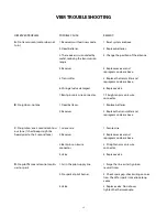
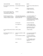
24VBM TROUBLESHOOTING
LED Code Table

