41
APPENDIX A
Third-Party Connections
The
24VBM
Burner Module was designed to be easily operated by power vent controllers or home
automation systems. Before any of these third party systems can be connected, the following steps
MUST be performed.
Step 1. Re-terminate Harness
The Vision Gas Fireplace cabinet comes with a blocked flue sensor and attached wiring harness. The
harness runs down from the sensor and lays at the bottom of the cabinet. The ring terminal on the
red wire must be replaced with the included 1/4” push terminal.
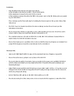
- Cut the ring terminal off of the red wire of the blocked flue sensor harness leaving as much wire
remaining as possible. Strip 1/4” of the insulation from the cut end and crimp the enclosed male push
terminal onto this stripped end. See Figure A-1.
Step 2. Connect Burner Control Module
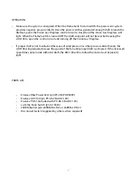
- Connect the red wire (male connector) from the blocked flue sensor harness to the red wire (female
connector) of the wiring assembly.
- Connect the violet wire (female connector) of the blocked flue sensor harness onto the
TR
terminal
of the control module.
- Connect the yellow wire to the
TH
terminal of the control module. See Figure A-2.
Step 3. Transformer Connection
- Wire the 24V AC transformer to a 120V AC branch circuit observing all applicable codes.
- Connect the red transformer lead (female) to the wire marked
24V +
and the green transformer lead
(male) to the
24V -
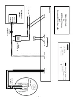
wire. See Figure 21 for a complete electrical schematic diagram.
At this point the
24VBM
is wired and ready for control. Connect the red and white leads (marked
and
SWITCH -
respectively) to a DRY CONTACT CLOSURE (not provided.) Do NOT energize
these leads beyond what is described in these instructions.
In a power vented application
and
SWITCH -
are wired to a DRY CONTACT controller which
will release the burner for operation after the draft has been proven.
In a home automation application
and
SWITCH -
are connected to a DRY CONTACT switch
that is controlled by the home automation system.
See your power vent controller or home automation system instructions for further details

