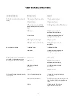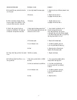
46
PLANNING
• Download the following from the Enervex website:
a) the installation manual for the PDS 1 Proven Draft Switch
b) the installation manual for the ADC100 Fan Control
c) the installation manual for either the RSIF in-line power vent
or
the RS chimney fan as required
by your installation
These manuals are the final authority for installing the Enervex parts in this system. Follow their
instructions.
• The PDS 1 must be mounted such that the silicone tubing reaches the vent stack per the
installation instructions.
• The Fan Disconnect Switch is required by some code jurisdictions for service. Since this switch
controls the fan, the system will not work when this switch is off.
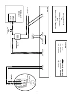
• The attached schematic is based on information in the ADC100 installation manual. When in
doubt, follow the ADC100 installation manual.
• Ensure that make-up air is available in the room in which the Vision Gas fireplace is installed. Your
project HVAC engineer should be consulted prior to this installation.
INSTALLATION
• Install a LO-TEMP SNAP SWITCH in place of the standard Vision Gas Fireplace snap switch.
• Ensure that all necessary jumpers are in place on the ADC100.
• The stack probe should be mounted as near as possible to the power vent and MUST BE FLUSH
with the inner wall of the B-vent. See detail in the PDS 1 Proven Draft Switch Installation and
Operating Manual.
• Adjust the fan speed with the ADC100 until your manometer reads -0.05” w.c. It may take several
changes to the local conditions (range hood on/off, nearby door open/closed, etc.) to arrive at a
satisfactory fan speed setting.
• Each of the three DIP switches in the ADC100 should be set to OFF.
• The silicone tubing from the stack probe is to be connected to the negative (-) side of the PDS 1.

