Page 7
Vista 38 ST See-thru Gas Fireplace
rev.110331
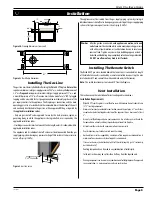
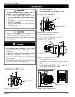
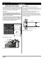
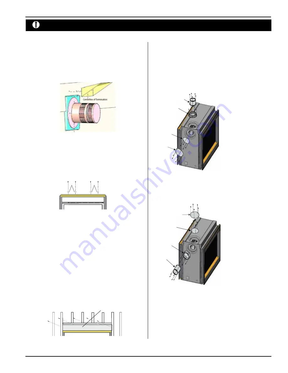
Figure 7.
Installing the nailing flange extension.
Nailing Flange Extension
1. Ensure that the two
long
mounting brackets are facing the bottom of the
termination. (See inset). This will provide more heat protection at the top of
the termination, where temperatures are highest.
2. Attach to the faceplate of the termination using four sheet metal screws.
Figure 5.
Installing the VSS Vinyl Shield heat guard.
Installing The Standoffs
To avoid elevated mantel temperatures, all
Vista 38 ST
Series gas fireplaces are
required to have the supplied standoffs installed.
The fireplace is supplied with two standoffs. Bend and install these standoffs
on top of the fireplace ensuring that the height of the standoff maintains a 6"
clearance.
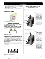
Figure 6.
Installing the standoffs.
Installing the Nailing Flange Extension
Once the fireplace is placed into the framed opening, the supplied nailing exten-
sion must placed along the top edge of the fireplace, and nailed in place to the
framing, as illustrated below. The supplied nailing extension must be placed
along the top edge of the fireplace and securely fastened in place to the lintel and
combustible wood framing.
Note:
The nailing flange extension can be substituted with a piece of
NON-
COMBUSTIBLE
material of the same size and thermal characteristics, i.e.; cement
board or equivalent.
Installation
Installing Heat Shield for Vinyl Siding
Converting the Vista 38 ST from
Top Vent to Side Vent
Top Vent
Use the following instructions to convert a
Vista 38 ST
for top vent or side vent use.
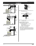
Figure 8.
Installing the top vent/side flue covers.
Top Vent
1. Install the 5" inner flue collar on
the top flue outlet and secure
the cap in place with four (4)
screws, as shown in
Figure 8
.
2. Install the 8" outer flue collar on
the top flue outlet, and secure it
with five (5) screws, as shown
in
Figure 8
.
3. Install the flue gasket material
and flue cover plate on the side
vent outlet . Fasten the cover
plate(s) with four (4) and five
(5) screws, as illustrated.
Figure 8a.
Installing the side vent/top flue covers.
Side Vent
1. Install the 5" inner flue collar
on the side flue outlet and
secure the cap in place with
four (4) screws, as shown in
Figure 8a
.
2. Install the 8" outer flue collar
on the side flue outlet, and
secure it with five (5) screws,
as shown in
Figure 8a
.
3. Install the flue gasket material
and flue cover plate on the top
vent outlet. Fasten the plate
with four (4) screws, and five
(5) crews as illustrated.
4. Install the 4" or 5" inner flue
collar and the 7" or 8" outer
flue collar in place on the
side vent outlet using five (5)
screws, as illustrated below.
5” Inner
Flue Collar
8” Outer
Flue Collar
5” Inner Flue
Cover Plate
8” Outer Flue
Cover Plate
5” Inner Flue
Cover Plate
8” Outer Flue
Cover Plate
8” Outer
Flue Collar
5” Inner
Flue Collar

