Page 8
Vista 38 ST See-thru Gas Fireplace
rev.110331
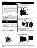
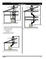
Installation Of Top Venting
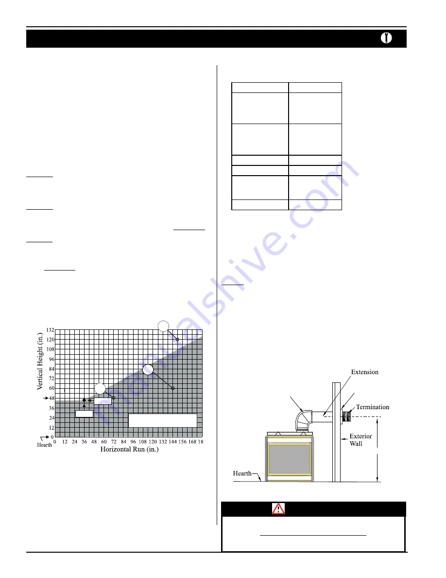
Figure 10.
Short horizontal installation.
Example:
A 10' section and an elbow used in conjunction with 3 ft. flex section (PFL-3) will,
when extended in a five foot chase, allow for a maximum horizontal run of twelve
and one-half feet from the center of the fireplace to outside wall and a minimum
of 7'6" when retracted in opposite direction.
See
Figure 11 and 12
.
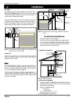
"D" flex sections and "E" solid sections may be used in conjunction with one
another in various possible horizontal vent installations.
NOTE: Flex section must
not exceed maximum horizontal length of 3 feet.
See
Figure 13
.
50”
RHS 101
Insulated
Sleeve
CRS101
WARNING:
Ensure RHS vent heat shields have a
minimum 1"
clearance on bottom and sides
from framing. Top must have
minimum 2"
clearance as shown.
46” NG
A
36” NG
C
48” LP
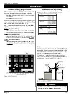
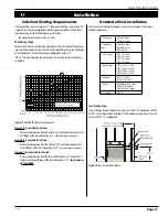
Figure 9.
Top Vent Venting Graph.
Top Vent Venting Requirements
Before you install any venting, you must determine whether the venting run will
be acceptable. Unacceptable venting can affect the fireplace's combustion.
•
for installations with horizontal venting runs of 0-16 feet, use the vent graph,
as described below
•
the maximum horizontal vent run is 16 feet.
Measure the vertical height from the fireplace hearth to the center of the termina-
tion and the horizontal run from the from the fireplace flue collar to the wall flange
of the termination. Plot on the venting graph,
Figure 9
with an 'X'.
If the 'X' falls on or above the top boundary of the shaded area, the installation is
acceptable.
Example A: (Acceptable Installation)
If the vertical dimension from the hearth is 112", and the horizontal run to
the wall flange of the vent termination is 150",
the installation is acceptable.
Example B: (Unacceptable Installation)
If the vertical dimension from the hearth is 48" and the horizontal run to the
wall flange of the vent termination is 72",
the installation is NoT ALLoWED.
Example C: (Unacceptable Installation)
If the vertical dimension from the floor of the fireplace is 60" and the hori-
zontal run to the wall flange of the vent termination is 144",
the installation
is NoT ALLoWED.
Powered venting to be used within
the shaded area of graph.
Installation
B
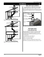
The following components are available for through-the-roof venting:
A - Termination
PVTK-1
B - Flex Sections
PFL-1 (12" section)
PFL-2 (24" section)
PFL-3 (36" section)
PFL-4 (48" section)
C - Rigid Sections
PEXT-1 (12" m/f section)
PEXT-2 (24" m/f section)
PEXT-3 (36" m/f section)
PEXT-4 (48" m/f section)
D - Support Ring and Plate
PSPXT-8
E - Firestop
PS-8
F - Roof Flashing
FRF-8 (flat roof)
PRF-7 (1/12 - 7/12 pt.)
PRF-12 (7/12 - 12/12 pt.)
G - Adaptor/Vent Reducer
PVA5487 (5"/8" to 4"/7")

