background image


VENTING 

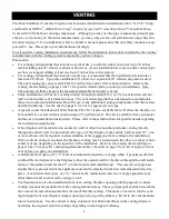
The West End Direct Vent Gas Fireplace has been tested and listed for installation with 4” X 6 5/8” Simp-

son DuraVent GS/Pro

®

Selkirk Direct-Temp

®

Security Secure Vent™, AmeriVent Direct™

Metal Fab Direct 

Vent and ICC


EXCELDirec

t


venting components.  Although you may use the pipe components (straight pipe, 

elbows, etc.) from any of  the listed manufacturers, you may only use the vent terminations (caps) listed in 

the chart on page 9.  For installations where a snorkel is needed, please note that only three snorkels are ap-

proved for  use.  Please plan your installation accordingly. 

For all specific venting installation requirements, follow the installation instructions included by the venting 
manufacturer with the venting system components you have chosen.   

Please note: 



For venting configurations that include no vertical rise, a total horizontal vent run of up to 30 inches  
(and including one 45° elbow) is allowed.  However, if your installation has room to add a vertical pipe 
section, we suggest adding at least one foot of vertical rise to the system. 



For venting configurations that include vertical rise, it is assumed that the installation will include at 
least one 90° elbow.  Up to three additional 90° elbows (or equivalent 45° elbows) may also be used.  
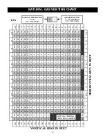
The total venting may not exceed 20 feet of vertical rise and/or 10 feet horizontal run.  Refer to the 
venting charts starting on pages 10 & 11 for specific details while you plan your installation.  Note:  
The number of elbows impacts the maximum allowable horizontal vent run. 



Many installations will involve venting directly through standard 2 X 4 or 2 X 6 construction exterior 
wall to a horizontal vent termination (cap).  The vent starter pipe has been designed to accommodate 
those two common installations without the use of any additional venting components other than a stan-
dard horizontal cap.  See the chart on page 9


for a list of approved vent caps. 



A special corner installation kit (Part Number CK-26-1) is also available that will allow the fireplace to 

be mounted in a corner without constructing a 45° partition wall.  This kit is available from your dealer 

and has its own installation instructions.  Please refer to those instructions for specific details regarding 

the installation using the kit.   



If the fireplace will be installed on an interior wall or other location that precludes venting directly 
through an outside wall to a horizontal vent cap, or if the distance to the outside wall exceeds 30”,  one 
or more elbows will be required to allow addition of the required vertical venting to the installation.  
When vertical venting is required, the fireplace venting may be terminated with either a vertical or hori-
zontal vent cap depending on the specifics of the installation.  Refer to the venting charts starting on 
pages 10 & 11


for specific venting requirements and see the chart on page 9


for a list of approved vent 

caps before you plan your installation. 



A minimum clear space of 1 1/2” must be maintained around the vent pipe where it penetrates the first 

combustible wall adjacent to the fireplace (either the outside wall for the direct-through-the-wall instal-

lation or the partition wall for the 45° or other interior wall installations).   The special vent pipe heat 

shields that are provided with the appliance must also be installed in the first wall adjacent to the fire-

place.  A minimum clear space of 1 1/2” must also be maintained where the vent pipe penetrates any 

other interior wall, exterior wall, ceiling or roof. 



The fireplace may also be installed in front of an exiting fireplace opening utilizing special co-linear 

venting components available from the venting manufacturers.  These systems split and then recombine 

the co-axial air and exhaust and allow the use of flexible venting.  This makes it easier to run the vent-

ing through the narrow fireplace damper opening to the top of the chimney.  Refer to the vent manufac-

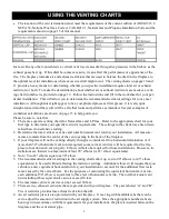
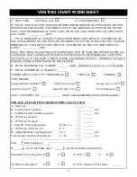
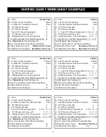
turers’ instructions.  Use the vertical venting column (0 feet Horizontal Run) in the venting charts to 

determine the required restrictor settings depending on the height of chimney. 


Summary of Contents for WEST END

Page 1: ...ctions is not followed exactly a fire or explosion may result causing property dam age personal injury or loss of life WHAT TO DO IF YOU SMELL GAS Do not try to light any appliance Do not touch any electrical switch do not use any phone in your building Immediately call your gas supplier from a neighbor s phone Follow the gas sup plier s instructions If you cannot reach your gas supplier call the ...

Page 2: ...ut être installé dans une maison préfabriquée mobile déjà installée à demeure si kes règlements locaux le permettent Cet appareil doit être uniquement avec las type de gaz indiqué sur la plaque signalétique Cet appareil ne peut être converti à d autres gaz sauf si une trousse de conversion est utilisée Ne pas utiliser cet appareils il a été plongé meme partiellement dans l eau Appeler un technicia...

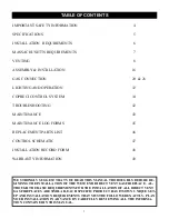
Page 3: ... 47 INSTALLATION RECORD FORM 48 WARRANTY INFORMATION 49 TABLE OF CONTENTS WE STRONGLY SUGGEST THAT YOU READ THIS MANUAL THOROUGHLY BEFORE BE GININNG THE INSTALLATION OF THE WEST END DIRECT VENT GAS FIREPLACE AL THOUGH THE BASIC REQUIREMENTS FOR THE INSTALLATION OF ALL DIRECT VENT GAS FIREPLACES ARE SIMILAR EACH SPECIFIC PRODUCT HAS ITS OWN UNIQUE SET UP AND INSTALLATION REQUIREMENTS THAT MUST BE F...

Page 4: ...ne and other flammable vapors and liquids The flow of combustion and ventilation air must not be obstructed Do not use this appliance if any part has been under water Immediately call a qualifed service technician to inspect the appliance and to replace any part of the control system and any gas control which has been under water Due to high temperatures the appliance should be located out of traf...

Page 5: ...be turned off if the appliance will not be in use for an extended period of time This appliance is equipped for use with the fuel type indicated on the rating plate This appliance has been certified by OMNI Test Laboratories Inc to ANSI Z21 88a 2007 CSA 2 33a 2007 Vented Gas Fireplace Heaters and CAN CGA 2 17 M91 Gas Fired Appliances for Use At High Altitudes The WEST END Wall Fire is approved for...

Page 6: ...s supply must be consid ered The location of the fireplace will also affect the venting requirements and you must be certain the lo cation will allow compliance with the venting requirements shown on page 8 You must also insure that your installation provides adequate accessibility clearance for servicing and proper operation Installation and repair should be done by a qualified service person The...

Page 7: ...f the dwelling building or structure served by the appliance It shall be the responsibility of the property owner to secure the services of qualified licensed professionals for the installation of hard wired carbon monoxide detectors In the event that the horizontally vented appliance is installed in a crawl space or attic the hard wired carbon monoxide detector with alarm and battery back up may ...

Page 8: ... Part Number CK 26 1 is also available that will allow the fireplace to be mounted in a corner without constructing a 45 partition wall This kit is available from your dealer and has its own installation instructions Please refer to those instructions for specific details regarding the installation using the kit If the fireplace will be installed on an interior wall or other location that preclude...

Page 9: ...will not be venting directly though an outside wall to a horizontal termination or if more than 30 of horizontal vent run is required some vertical vent rise will be required for the fire place to function and vent properly Elbows will also be required for those installations However in stallations are limited to a maximum of four 90 elbows or 45 elbow equivalents 4 Note Two 45 elbows equal one 90...

Page 10: ... 4 A 4 A 4 A 4 A 4 A 4 A 4 A 4 A 4 A 4 A 4 A 4 10 9 A 4 A 4 A 4 A 4 A 4 A 4 A 4 A 4 A 4 A 4 A 4 9 8 A 4 A 4 A 4 A 4 A 4 A 4 A 4 A 4 A 4 A 4 A 4 8 7 A 4 A 4 A 4 A 4 A 4 A 4 A 4 A 4 A 4 A 4 A 4 7 6 A 4 A 4 A 4 A 4 A 4 A 4 A 4 A 4 A 4 A 4 A 4 6 5 A NU A NU A NU A NU A NU A NU A NU A NU A NU A NU A NU 5 4 NU NU NU NU NU NU NU NU NU NU NU NU NU NU NU NU NU NU NU NU NU NU 4 3 NU NU NU NU NU NU NU NU NU ...

Page 11: ... 11 10 B 1 B 5 B 5 B 5 B 5 B 5 B 5 B 5 B 5 B 5 B 5 B 5 10 9 B 5 B 5 B 5 B 5 B 5 B 5 B 5 B 5 B 5 B 5 B 5 9 8 B 5 B 5 B 5 B 5 B 5 B 5 B 5 B 5 B 5 B 5 B 5 8 7 B 5 B 5 B 5 B 5 B 5 B 5 B 5 B 5 B 5 B 5 B 5 7 6 B 5 B 5 B 5 B 5 B 5 B 5 B 5 B 5 B 5 B 5 B 5 6 5 B 4 B 4 B 4 B 4 B 4 B 4 B 4 B 4 B 4 B 4 B 4 5 4 A 4 A 4 A 4 A 4 A 4 A 4 A 4 A 4 A 4 A 4 A 4 4 3 A 3 A 3 A 3 A 3 A 3 A 3 A 3 A 3 A 3 A 3 A 3 3 2 A NU...

Page 12: ...SE THAT MUST BE COUNTED D TOTAL NUMBER OF 90 ELBOWS _______ NOTE SNORKELS COUNT AS 2 90 ELBOWS E TOTAL NUMBER OF 45 ELBOWS _______ TERMINATION CAP TYPE HORIZONTAL VERTICAL SNORKEL VENT BRAND Simpson DuraVent GS Pro Selkirk Direct Temp Security Secure Vent AmeriVent Direct Metal Fab Direct Vent ICC EXCELDirect VENT CAP MODEL NO _______________ NOTE SEE APPROVED VENT CAPS ON PAGE 8 EXHAUST AND AIR I...

Page 13: ...t Restrictor Required B Air Restrictor Tabs Open 5 A Fuel LP Gas B Total Vertical Vent Rise 2 feet C Total Horizontal Vent Run Actual 10 feet D 90 Elbows Needed 2 E 45 Elbows Needed 0 F Total 90 Elbows Equivalent 2 0 x 2 G 90 Elbows in Excess of 2 2 2 0 H Additional Horiz Feet Equivalent 0 x 3 0 I Total Horiz Vent Run Equivalent 10 0 10 Use LP Gas Chart Settings for 2 feet Vertical Rise 10 feet Ho...

Page 14: ...ERTICAL TERMINATION The illustration below shows some of the many ways the fireplace may be installed in the home This in cludes interior and exterior wall installations corner installations and horizontal and vertical vent termina tions ...

Page 15: ...15 VENT TERMINAL CLEARANCES Venting terminals shall not be recessed into a wall or siding ...

Page 16: ...dling the right panel to avoid damaging the cable or pad 3 Next remove all remaining packing material from the car ton 4 Lift the firebox and the fireplace mounting plate as a unit up and out of the carton The best place to lift is at sides Remove the fireplace mounting template from the face of the fireplace You should now have all of the parts as shown in the illustration below 5 Next unpack the...

Page 17: ...nt pipe and to allow for installation of the vent heat shields that are provided with the fireplace Follow the hole size requirements that are provided below exactly to avoid problems If the location you have chosen does not allow for 1 1 2 clearance to wooden framing in the wall modifications to the wall structure must made to obtain the needed vent pipe clearance 3 All required minimum clearance...

Page 18: ...heetrock or plas ter and lath outer wall sheathing and outer wall covering and any adjacent internal wall materials like insulation 2 Scribe a 9 5 8 diameter hole around the vent pass through center mark using a compass 3 Use a long drill 1 8 diameter that is held square and level to the inside wall to transfer the vent pass through center location from the inner wall covering through to the outer...

Page 19: ...below the vent opening The blocking should be above and below the 9 5 8 vent opening you made in the wall and should not ob struct that opening The blocking should extend to adjacent wall studs 7 Next mark and cut a 9 5 8 diameter hole through the wall covering on the back side of the partition wall using the locating hole you drilled in Step 2 8 When installing the fireplace on a partition wall t...

Page 20: ...cation If not the wall should be reconstructed to provide the needed support 3 Before the mounting plate can be lagged to the wall the two tabbed sections of the telescoping vent pipe heat shields that you set aside earlier must be attached to the mounting plate Each heat shield half is held in place with three sheet metal screws provided The inner shield half smaller di ameter is installed from t...

Page 21: ...glass frame forward a few inches 13 Wrap your fingers around the frame and hold the glass and frame together while you lift the frame up and out of the lower glass retainer Set the glass and frame assembly aside in a safe place 14 Carefully place the fireplace with the front down on a protected floor 15 At this point it is necessary to determine whether your installation will require the addition ...

Page 22: ...maintain the most symmetrical pattern pos sible The first tabs bent must be opposite each other and ori ented horizontally If only one tab is specified orient the ring over the pilot holes so the split tabs are oriented horizontally and bend up two opposing half tabs Additional tabs should be evenly spaced relative to the first two With the appropri ate tabs bent re align the mounting holes in ove...

Page 23: ...ckets Note The weight of the fireplace is carried only on the top brackets The bottom brackets function simply to keep the bot tom of the fireplace from moving Refer to the adjacent illustration 14 If the fireplace is properly positioned on the brack ets the vent starter pipe and vent heat shields should be concentric when viewed through the vent pass through in the wall Go outside and look in the...

Page 24: ...inner and outer vent termination pipes onto the vent starter pipe taking care to align the inner and outer pipes to prevent damage 5 Slide the vent termination cap into the siding re cess or vinyl siding shield until it bottoms out Note The rear surface of the vent termination will push the telescoping vent pipe heat shields inward When the vent termination is in place the heat shields will just t...

Page 25: ...imum of 10 feet of horizontal run If more than two 90 elbows or equivalent 45 elbows are needed for your installation the maximum amount of horizontal run allowed is reduced See the venting section starting on page 8 for specific in formation It is important to plan the installation in advance so that you can accurately locate the any wall or ceiling pass through s and the vent termination on the ...

Page 26: ...pply line where it penetrates the wall fireplace mounting plate and the inlet to the regulator on the fireplace This will allow gas to be shut off to the fireplace by simply removing the fireplace surround to gain access to the shut off valve 5 The fireplace and its inlet regulator and main burner valve must be disconnected from the gas supply piping system during any pressure testing of that syst...

Page 27: ...c Module 7 The remote handset is powered by two AA bat tery The access panel is located on the back of the handset and simply snaps open to provide access to the battery compartment Install two batteries as shown on the label inside the remote control bat tery compartment 8 Replace the remote handset access panel BATTERY PACK Placing the Burner Glass Media The burner glass media poly bag that you ...

Page 28: ...a gasket material that covers the full bottom surface Use care in handling the relief doors to avoid damage to the gasket material 2 The first illustration below shows one of the two sets of relief openings and relief door retainers 3 The relief doors include line up tabs that correspond to slotted retainers on the firebox 4 Tip each relief door enough to allow the rear line up tab to engage the r...

Page 29: ...care to center the frame from left to right 3 Once the bottom edge is in place move your fingers out of the way and press the top of the frame against the firebox while pushing down to be sure the frame is fully engaged in the frame retainer 4 Hold the frame in place with one hand and insert the four glass frame fasteners along the top edge of the glass frame Tighten the fasteners until they are h...

Page 30: ...ill find this next to the electronic control module Hold the side panel up near the fireplace and connect the cable end to the touch pad connector Note that arrow on the on the cable end connector must align with the 5 on the touch pad con nector in order to function correctly 8 Route the cable through the cutout in the fireplace mounting plate flange and position the right side panel so it aligns...

Page 31: ...mating brackets on the fireplace top You might find it eas ier to engage one bracket and then the other Lower the surround until both bracket sets are fully mated 5 Carefully swing the bottom of the surround toward the base of the fireplace until the catch plates on the bottom flange of the surround are aligned with the adjustable locating screws on the bottom flanges of the lower surround mountin...

Page 32: ...s the pilot Do not try to light the pilot by hand 3 If using the Remote Handset push the button until you hear an audible signal to insure the appliance is off 4 Wait five 5 minutes to clear out any gas Then smell for gas including near the floor If you smell gas STOP Follow B in the safety information above If you don t smell gas proceed to step 5 or 6 5 If you are using the Remote Handset press ...

Page 33: ... burner has been in operation for a few minutes the flames should look like those in the illustration below Note The flame height will vary depending on the firing rate setting but flames should be evenly distributed across the full width of the burner FIG 1 FIG 2 FIG 3 CORRECT PILOT FLAMES 10 To turn the appliance off completely push and release the OFF button on either the Remote Handset or Manu...

Page 34: ...ate that the system has accepted the order and the flame will light on the High setting To decrease the flame level press the DOWN button A beep and a flash of the LED indicate that the sys tem has accepted the order and the flame will decrease to Medium setting Pressing the DOWN button again and the flame will decrease to Low setting Pressing the Down button a third time and the fireplace goes to...

Page 35: ...ime C Signal strength D Selected working mode E Selected setting F Current flame status G Current fan status Not Applicable on this appliance H Current room temperature I Child lock status J Button labels explained below NOTE The bottom row of the screen is indi cating buttons functionality In this case 1 button decreases the flame level 2 button increases the flame level 3 Back button goes back t...

Page 36: ...sible that the remote is locked in the OFF screen to unlock it just press the button below Unlock and then OK 2 3 Switching on Once the remote is unlocked press ON left button and OK middle button A beep from the control unit will be heard and the ignition process starts Note that while in operation the RF signal strength indicator dis appears Wait until the current flame status displays Pilot 2 4...

Page 37: ...37 COPRECI R emotion CONTROL SYSTEM ...

Page 38: ...in the configuration menu This specified the maximum permitted room temperature This temperature can never be set higher than 104º F 40º C It is recommended you set to 95º F 35ºC Auto Thermostatic Mode If Auto is pressed in the initial screen 77º F 25º F appears as the desired temperature in the se lected setting In the bottom row and ap pear indicating that we can change the desired temperature v...

Page 39: ...appliance will heat until this temperature is reached Comfort Temp The comfort temperature is set as the desired temperature and the appliance will heat until this temperature is reached Finally to launch the program mode in the main menu set Program to On and select the desired Program Type Daily or Weekly 2 7 Other features How to locking and unlock the remote child lock To unlock the remote pre...

Page 40: ...you get to main screen PS If pairing has been attempted previously and has not been achieved try the follow ing Press and hold the OFF button for 40 seconds Set the channel on channel A Select On in the pairing setting Unplug the batteries from the control unit wait 10 seconds and plug the batteries back in Once the valve has finished moving repeatedly push press and release the S1 but ton yellow ...

Page 41: ...e possible range of values is 77 104 F 25 40 C Suggested setting is 95 F 35 C Channel There are three different channels available A Band C These different channels make it possible to have more than one appliance each with its own remote If you only have one unit the channel setting should remain on A If you need to change the channel just press Select choose one of other channels and then reset ...

Page 42: ...42 TROUBLESHOOTING ...

Page 43: ...so it is very important to support both the glass and the frame when handling Place your thumbs on the outside of the glass frame and wrap your fingers around the frame and onto the glass Squeeze the frame and glass while moving Carefully lift the glass frame and glass up and off the fireplace Set the glass and frame aside on a padded surface If the glass is broken do this over spread out newspape...

Page 44: ...maintenance appointment the service person should clean the burner and firebox To gain access to the firebox and burner follow the instructions beginning on page 34 of this man ual DO NOT USE A VACUUM CLEANER TO CLEAN THE GLASS BURNER MEDIA A vacuum cleaner may be used to clean the metal parts of the firebox Leave the glass burner media in place Use a soft brush to clean the burner glass media If ...

Page 45: ...onnections Other __________________________ MAINTENANCE LOG Date of Service ____________________ Serviced By ______________________ Service Performed Inspect Venting Clean Burner Firebox Clean Control Area Clean Convection Air System Leak Test Gas Connections Other __________________________ Date of Service ____________________ Serviced By ______________________ Service Performed Inspect Venting C...

Page 46: ...dia Clear 26 511 Valve Control Module Copreci 46 504 Burner Module NG 26N 901 Manual Control Panel Copreci 46 505 Burner Module LP 26P 901 3 C Battery Holder Copreci 46 506 Firebox Panel Rear 26 512 Remote Handset Copreci 46 507 Firebox Panel Left 26 513 Gas Valve Copreci 46 515 Firebox Panel Right 26 514 External Regulator Maxitrol 26 516 For replacement parts and customer service contact your WE...

Page 47: ...ntrols Wiring errors can cause improper and dangerous operation Verify proper operation after servicing A B C D E F G H Caution Label all wires prior to disconnection when servicing the controls Wiring errors can cause improper and dangerous operation Verify proper operation after servicing ...

Page 48: ...low that describes the details of the installation Having this writ ten record of installation information available will greatly expedite trouble shooting should any problem arise with your stove The installer should keep a duplicate of this form for their records ...

Page 49: ...49 ...

Page 50: ...50 V13EH 1 26 2010 EUROPEAN HOME A division of Europa Ja Inc 376 Washington St Suite 203 Malden MA 02148 USA www europeanhome com t 781 324 8383 f 781 324 8384 ...

Reviews: