background image

User manual - JETPRO 100-7, 120-7, 130-7 

202002-400A-ENG

P2

You just acquired one of our 
machines and all the team 
of Europe Projection thanks 

you  for  the  confidence 

you have granted us.

Manufacturer of professional 
equipments for paint and 

fillers,  we  have  put  our 
know-how  for  25  years 

at the service of the 
users of our machines.

Our technical & commercial 
team is at your disposal 
for any further information 
you may need about the 
machine you just acquired.

EUROPE PROJECTION

228, avenue Olivier Perroy

13790 ROUSSET

Tél : +33 (0)4 42 29 08 96

contact@euromair.com

SUMMARY

1. USER MANUAL ............................................................. p.  3

1.1. Importance of the manual .........................................p.  3
1.2. Receivers of the manual ............................................p.    3   

2. WARNING .................................................................... p.  4

2.1. Safety .....................................................................p.  4
2.2. Electric connection ...................................................p.  6
2.3. End-of-life of the product ..........................................p.  6

3. YOUR MACHINE ........................................................... p.  7

3.1. Description ..............................................................p.  7
3.2. Technical characteristics ...........................................p.  7

3.3. Identification of the components

 ................................p.  8

4. USE OF THE MACHINE ................................................. p.10

4.1. Prerequisites ............................................................p.10
4.2. Starting up - Use of plaster/paint................................p.11
4.3. Starting up - Use of droplet .......................................p.12
4.4. Error codes ..............................................................p.13

5. DEFECTS AND REMEDIES ............................................. p.13

6. CLEANING PROCEDURE ............................................... p.14

6.1. After plaster/paint use ...............................................p.14
6.2. After droplet use ......................................................p.15

7. MACHINE DECLARATION OF CONFORMITY .................... p.16

8. SPRAY-GUN DECLARATION OF CONFORMITY ................ p.17

9. WARRANTY CONDITIONS .............................................. p.19

Summary of Contents for 30801

Page 1: ...l 33 0 4 42 29 08 96 Fax 33 0 4 42 53 44 36 SAS au capital de 400 000 RCS Aix en Provence B 394 961 510 NAF 2892 Z Intracom FR 54 394 961 510 JETPRO 100 7 120 7 130 7 R f 30988 30801 30807 User manual...

Page 2: ...l 33 0 4 42 29 08 96 contact euromair com SUMMARY 1 USER MANUAL p 3 1 1 Importance of the manual p 3 1 2 Receivers of the manual p 3 2 WARNING p 4 2 1 Safety p 4 2 2 Electric connection p 6 2 3 End o...

Page 3: ...caused by the non compliance of the safety standards and rules This manual must be kept near the machine within reach of the user and held in good condition until the final destruction of the machine...

Page 4: ...irect a water jet or flammable liquid on the machine Never direct an air jet or product jet on a person or an animal Do not touch warm surfaces of the equipment Always wear adequate body protections g...

Page 5: ...e as well as children and animals In case of installation of the machine on scaffolding or a plan above ground level attach the machine to avoid any fall while operating Do not install the equipment o...

Page 6: ...ive to unwind it entirely otherwise the equipment can be damaged The section must be proportional to the length of the cord 2 3 END OF LIFE OF THE PRODUCT At its end of life the machine must not be el...

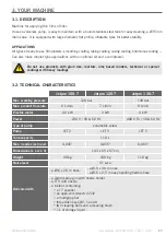
Page 7: ...Jetpro 130 7 Max working pressure 120 bar 130 bar Max product flow rate 6 L min 7 L min 9 L min Electric motor 2 2 kW 3 kW 4 kW Power 230 V 50 60 Hz 400 V Tri 50 60 Hz Type of pump volumetric screw Pu...

Page 8: ...7 202002 400A ENG P8 3 YOUR MACHINE continued 3 3 IDENTIFICATION OF THE COMPONENTS A Product outlet B Filter holder C Pump D Manometer E Drain valve F Automatic lubricator G Spray gun H Nozzle I Cont...

Page 9: ...3 3 IDENTIFICATION OF THE COMPONENTS continued 1 Start Stop A1 Motor speed or pump pressure in display 2 Forward running B1 Network voltage display 3 Backwards running L1 Power on light 4 Increase the...

Page 10: ...ly the pump is unblocked Empty the water Check every month that the machine s automatic lubricator is working properly The level of grease in the cartridge should decrease steadily The absence of grea...

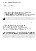
Page 11: ...on 2 and wait until the product comes out of the spray gun 10 As soon as the product comes out of the spray gun press the button 2 again then close the spray gun 11 Install the nozzle holder and the n...

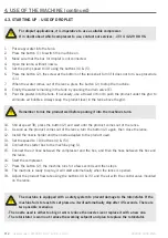
Page 12: ...the nozzle holder and the nozzle adapted to the product used 13 Set the speed to 10 buttons 4 5 14 Connect the starter box to the machine plug J 15 Connect the air hose between the compressor and the...

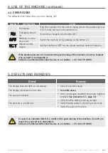
Page 13: ...splay does not light up no display Verify the power supply The display indicates an error code See table above The pump is blocked After a prolonged standstill the pump might be blocked See procedure...

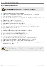
Page 14: ...and reconnect it to the machine 12 Still at speed 30 turn the machine on the product starts to come out 13 When the ball comes out of the hose repeat the operation 14 Clean the spray gun then put it...

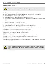
Page 15: ...leaning the pump nose filter product outlet 11 Disconnect the lance from the hose 12 Put the cleaning ball in the hose and reconnect it to the machine 13 Still at speed 30 turn the machine on the prod...

Page 16: ...COMPLIES WITH THE ARTICLE the R 233 73 article of the Labour Code THE DIRECTIVES Machines 2006 42 CE Low voltage 2014 35 UE CEM 2014 30 UE ROHS 2011 65 UE AND WITH THE STANDARDS NF EN ISO 12100 NF EN...

Page 17: ...OJECTION Model Spray gun Working pressure 19 MPa COMPLIES WITH THE ARTICLE the R 233 73 article of the Labour Code THE DIRECTIVE Machines 2006 42 CE AND WITH THE STANDARD NF EN 1953 ROUSSET JANUARY 20...

Page 18: ...User manual JETPRO 100 7 120 7 130 7 202002 400A ENG P18...

Page 19: ...which were totally or partially dismantled Defective equipment will be removed by us Any shipment of equipment by the customer will be at its own expense The guarantee will be subject to the presenta...

Page 20: ...0 ROUSSET T l 33 0 4 42 29 08 96 Fax 33 0 4 42 53 44 36 SAS au capital de 400 000 RCS Aix en Provence B 394 961 510 NAF 2892 Z Intracom FR 54 394 961 510 User manual JETPRO 100 7 120 7 130 7 202002 40...

Reviews: