4
Modular Push Bar Panic Bolt with Vertical Rods Rev.7
Installation
4
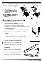
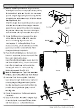
1) Remove 8 cover fixing screws from
main cases (Items 1A and 1B) (See
Fig 4.1)
2) Offer Panic Bolt Box to door in
location obtained at preparation
remembering centre line mark is
follower height
Note: Distance from door frame
edge to Panic Bolt Box must be
Min 10mm
3) Mark 6 fixing holes from obtained position.
Fig 4.1
Fig 4.2
5) Measure distances (‘A’ & ‘B’) from the Panic Latch Box (1A).
See Fig 4.2
‘A’ Top of Panic Bolt Box (1A), to underside of door jamb
‘B’ Bottom of Panic Bolt Box (1A), to the final floor level
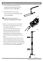
Fig 4.3
6) Cut tubular rods (Items 2 & 3) to the lengths
measured less 88mm for both.
See Fig 4.3
Note: Both rods have pre-drilled holes for
fitting to the Rod connectors (Items 18)
therefore ensure the bars are cut at the
opposite end.
Remove any burrs and insert Knurled plugs
(Items 12) fully into cut ends of rods taking
care to use a wooden block to support the
opposite end when knocking the plugs into
position.
See Fig 4.3
Note: If fitting External Locking attachment, rotate
follower to suit hand of door.
Right Hand door, rotate follower fully “clockwise”.
Left Hand door, rotate follower fully “anti-clockwise”.
The External Locking Attachment now needs installing according
to it’s supplied instructions.
4) Secure Panic Bolt Box (1A) to door using 6 screws (Item 15)


