5
Modular Push Bar Panic Bolt with Vertical Rods Rev.7
Installation – (continued)
4
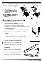
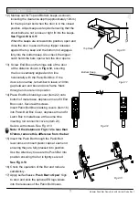
7) Fit rod connectors to rods using 2 socket
headed cap screws (Items 28). Secure with
supplied Allen key (Item 13)
See Fig 4.4
8) Remove Panic Bolt box from door and
insert rod connectors onto angled plates inside
main body
See Fig 4.5
Note: The Push bar lever must be
depressed to enable fitting of connectors
Fig 4.4
Fig 4.5
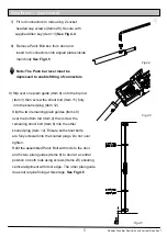
9) Slip over one plain guide (Item 8) onto the top rod
(Item 3) then screw the shoot bolt (Item 11) fully
into the knurled plug (Item 12)
Slip the two remaining plain guides (Items 8)
over the bottom rod (Item 2) then screw the
remaining shoot bolt (Item 6) into the other
knurled plug (Item 12). Ensure both shoot bolts
are fully screwed into the knurled plugs. Do not over
tighten.
Refit the assembled Panic Bolt with rods to the door
and fix two plain guides (Items 8) to door at a central
position on both rods using screws (Items 23) ensuring
vertical alignment with door edge. The other plain guide
does not require fixing at this stage.
See Fig 4.6
Fig 4.6


