7
Modular Push Bar Panic Bolt with Vertical Rods Rev.7
Installation – (continued)
4
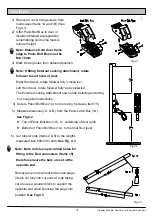
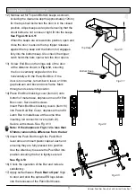
12) Mortise out for Top and Bottom keeps as shown,
including the clearance depth (approximately 12mm)
for the top shoot bolt when the door is in the closed
position. Adjust keeps as required ensuring that the
shoot bolts are not a loose or tight fit into the keeps.
See Figs 4.10 & 4.11
When the keeps are screwed into position, open and
close the door to ensure the top tripper releases
against the top keep and the bottom rod engages
fully into the bottom keep. Also check the tripper
catch holds the bars open when the door opens.
Top Keep
Fig 4.10
Fig 4.11
Bottom Keep
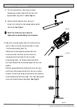
13) Screw End Box on the hinge side of the door
at the distance shown in
Fig 4.12
, ensuring
the box is vertically aligned and in line
horizontally with the Panic Bolt Box. If the
door is too narrow, remember to leave a 10mm
gap between end box and door frame. Mark
through and secure into position.
14) Place End Box blanking cover (item 22) onto
bottom of metal base, depress arm and fit End
Box cover. Secure with screws.
Insert Panic Bolt Box blanking covers (item 16)
into Panic Bolt Box Cover, depress arm and fit
Latch Box to metal base at the same time
inserting rod connector covers (item 23).
Secure with screws. See Fig 4.13
Note: If the distance in Fig 4.12 is less than
674mm, remove this difference from the bar
15) Insert the Push Bar through the Panic Bolt
lever arms and insert plastic caps at each end
ensuring they are fully pressed into position.
Use the Allen key to secure the Push Bar into
position ensuring the bar is tightly secured.
See Fig 4.13
16) Check the operation of the Bar and rods are
satisfactory.
17) Apply self adhesive ‘
Push Bar to Open’
Sign
to door and stick the optional ES logo labels
into the recesses of the Panic Bolt boxes .
Fig 4.12
Fig 4.13
12mm


