10
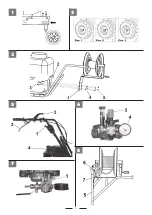
WHEELS INSERTING (3 POSITIONS) DEVICE : (Fig.2) –
The motorpump is equipped with a special device named “ FORK – 3 POSITIONS”. In
position 1 ( free) the wheel is free turning on the shaft in order to allow the machine tom ove even if the engine is switched off ( for example in case the
operator wants to drive the unit out from garaging as it is better to avoid to switch the engine on in close areas or not well ventilated and the exhaust
gas is dangerous).
In position 2 ( stop) the wheel is integral with the shaft , and it i sto be considered as a driving wheel, i.e. ready to work , which is normally the most
used way. Such position is COMPULSORY when you are using the motorpump on slopes. Position 3 ( semi-differential) the wheel can move for about
1 free turn on the shaft in order to allow the reversal of speed.
ATTENTION ! All the actions performed on the 3 positions fork should be done when the engine is switched off and on a flat surface.
SPRAYING (FIG. 6-7-8)
The motorpump had been designed for a single use and it is not allowed to perform spraying operations when the machine
moves. You need to switch the engine on to go near the area to spray ( SEE CHAPTER : HOW TO USE THE MACHINE) and insert the device intake
using the proper lever (1)and turn it on position “I” : this way you shall start a continuous flow cycle of liquid into the tank . Such liquid is passing into the
pump and comes back into the tank again. It IS necessary to wait for a while that the am cycle is starting then you need to put the tap on “ON” position
and adjust the requested service pressure using the red handle (3) . The reached level is shown by the manometer (4).
Now you can start spraying : hold the nozzle (5) and press the lever (6). A slight pressure will make the nebulized liquid to come out , while pressing the
lever all the way you will see a more powerful jet/stream. When the operator finishes his job you should put the nozzle into the corrresponding housing
(7) , put the lever (1) on position “O” and switch the engine off.
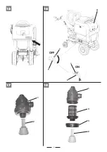
IDENTIFICATION DATA FOR THE PRODUCT IN USE (FIG. 15)
On the unit it is installed a label-holder with its own label where the user is obliged to
show the name of the pesticide he is using, such label holder is placed on the front side of the tank.
HANDWASHING SYSTEM (FIG. 16)
The unit is equipped with an independent tank (A) capacity di 10 Lt which is used to rinse the hands or other parts
of the body that accidentally come in contact with the product in use. In order to make the water to come out from the tank it is necessary to rotate
the lever (1) placed on the tap (2) clockwise by 180° . To stop the water please perform the a.m. operation in reverse.
IMPORTANT ! TANK (A) IT IS ALLOWED TO PUT WATER ONLY.
RANGE AND TYPE OF SPRAYER, and NOZZLE, FILTER USED:
Sprayer: Tube steel lance with nozzle stainless Ø1.5 mm, use between15-60 Atm (standard).
You can use any type of nozzle (expl simple miter nozzle etc.., It is important that its application range to be between 15-60 Atm.
Head for turbo nozzle lever: Nozzle Ø1.5 mm, ceramic, may also be used with nozzle holes that varies from a minimum of Ø1 mm to a maximum of Ø3 mm.
The combination of the above mentioned nozzle, with head turbo nozzle with Ø1.5 mm to 30 bar, it has a range of up to 9 meters; if at the same pressure
(30 bar) can be adopted nozzles with greater holes than Ø1. 5 mm, the range/throw increases. Example: 30 Bar, nozzle with Ø 3 mm hole, you get a
range of 11 meters. Group filter: filtering capacity 60 l / min., Thread fitting 1 “1/4, 18 mesh
SERVICING:
During all services operations, cleaning and assembly of the accessories, it is necessary to switch the pipet of the engine sparkling plug
off. Before every use , please verify the seal of the connectors and gaskets in order to avoid any liquid leaks and consequent pollution danger. Please
also check, from time to time, the pump oil level and , if it is necessary, please fill it in. ( see the pump instructions booklet here enclosed) . When you
screw the cap up , please take care not to tighten it too much in order to avoid the thread to damage.
CLEANING THE IRRORATION SYSTEM FILTER (Fig. 17 and 18): The spraying system is equipped with a filter (1), placed in front of the pump. If it is
necessary to drain the filter, with the engine off, unscrew the yellow cap (2), pressing at the same time upwards.
ATTENTION! With this operation the liquid contained in the filter will be emptied, prepare in advance a suitable container to prevent spills.
If a complete cleaning is necessary, remove the filter element (4), unscrewing the ring nut (3).
ATTENTION! Before resuming work, make sure you have reassembled the filter correctly, following the previous instructions in reverse.
GARAGING AND RECURRING SERVICING:
Please keep all the nuts , the washers and the screws well tightened in order to allow the
machine to properly/safety working. Please make the unit to cool before garaging it and , anyhow, do not leave gasoline in the tank in inside areas
where vapours can come into contact sparks and/or flames.
To reduce the danger of fire to break out , please keep the engine , the silencer and the gasoline stocking area free from leaves, grass or greasy materials.
Please proceed the here under mentioned operations ( with the term “
hours
” we mean the working hours of the machine).
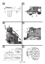
GEARBOX (Fig. 14)
OIL LEVEL CONTROL :
Lubricating oil : please use oil SAE 80. Please verify the oil level every
60
hours . Please put the machine on level land,
unscrew the cap (1) and check the oil to be at a hole lower side in case it is necessary to restore the oil level , fill it in from the same hole up to the oil
quantity comes out. Then screw up the cap again.
OIL CHANGE :
please change the oil every 150 hours. The oil discharge should be performed when the unit is still warm. Unscrew the cap (1), incline
the unit to completely empty it , then , fill it in using the same hole (1) up to the oil quantità starts to come out. Then screw the cap again.
Attention : the waste oil is a polluting material . Please do not waste it in the surroundings, but call to specialized gathering centres.
TROUBLES AND REMEDIES :
please see the pump instructions booklet.
DISASSEMBLY OF THE PUMP-TANK SET : (FIG. 9-10-11-12)
In case it is necessary to disassemble the spraying set composed of
the pump and the tank (for example to change it with other accessories) . It is necessari to remove the belts protection cover (part.1) , unscrewing the
screw (2) and taking out the end (3) from the frame slot. The using a punch (4) make the belts to come out (5) from pulley seats and, following, press
the handle (6) and meke the set to rotate forward.
To complete the disassembly operations it is enough , on both sides of the machine, to remove the pin (7) and press , in the same time, using a punch
on the pivots (8) in order to allow the spraying set unclamping .
TECHNICAL SPECIFICATIONS :
2 gears gearbox( 1 f 1 reverse) – Endless screw transmission in oil bath + belts - tank lt. 120 with
filter – Membrane pump RPM max 700 – Pressure max 30 Bar - max capacity : 20 lt/minute - Winding tube support equipped with 25 mt tube + hose pipe.
NOISE AND VIBRATION LEVELS :
acoustic power value to operator’s ear , UNI En 1553, Lpa = 81,6 dB(A) (79,1 dBA in working conditions),
with a uncertainty value K = ±1,1 dB(A). Acoustic power value according to directive 2000/14/CE, Lwa = 93,8 dBA , with a uncertainty value K = ±1,3
dB(A). Average vibration value for the handlebars during transport , according to UNI En 1033, i.e., 6,38 m/s
2
, with a uncertainty value K = ±3,19 m/s
2
.
ACCESSORIES :
standard tank complete of plate, handle and quick camping device. The snow front blade with adjusting handle. Snow chains
pair for pneumatic wheels. Sheet platform cm. 59x81 equipped with a plastic collector.
EN
Summary of Contents for Carry Sprayer
Page 2: ...2...
Page 3: ...3 1 3 2 5 6 7 8...
Page 4: ...4 11 12 13 14 9 10...
Page 5: ...5 15 16 A 1 2 OFF ON 1 2 17 18 1 2 1 2 4 3...
Page 19: ...19...
Page 20: ...cod 350065110 10 04 2018...


