BA_S011
Operation Manual
EUROTEC Antriebszubehör GmbH | Bildstock 37 | DE-88085 Langenargen | sales@eurotec-shop.com | www.eurotec-shop.com | 19.11.2015 | Seite 3 von 5
The equipment may only be operated in completely assembled status.
Never disconnect energised cables or systems.
5.
Mounting on pneumatic actuators
The limit switch boxes can be mounted quickly and easily on your actuator with the delivered screws according to VDI/VDE 3845.
1.
Bring the actuator in the end position in which the flute of the actuator shaft is in parallel to the actuator housing.
2.
Attach the switch box with the suitable mounting bracket to the actuator.
3.
The mounting bracket can now be fastened on the actuator with the 4 delivered screws.
4.
Release the 4 cover screws and open the switch box. Do not unscrew them too far so that they do remain plugged into the cover.
5.
Lead the system cable through the cable gland into the switch box housing and connect the individual leads to the terminal block.
Consider thereto the wiring diagram on the according data sheet or on the switch box cover and connect the housing to the potential
equalization.
6.
Close the switch box with the cover. Take care that the sealing of the cover is in proper position and tighten the screws firmly.
6.
Mounting on manual valves
The limit switch boxes with F05 interface at the bottom side of the housing can also be mounted on manual valves by using our mounting kit
“MSH”. Thereto your manual valve needs a top flange according to ISO 5211 (F03 - F16) and a threaded bore hole in the valve shaft. For
detailed assembly instructions please consider the operation manual of the “MSH”.
7.
Electrical connection
The permitted sheath diameters are indicated on the according data sheet of the limit switch box. The circuit diagram is indicated on or
inside the limit switch box cover as well as on the according data sheet.
Take care that the cable gland body, which is mounted to the housing, does remain in it’s position when
tightening the cable gland nut. Please use 2 fork wrenches for this procedure. One to prevent the cable gland
body from turning and the other to tighten the cable gland nut. If the cable gland sealing leaves it’s proper
position, it will influence the level of the protection by enclosure (IP).
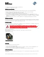
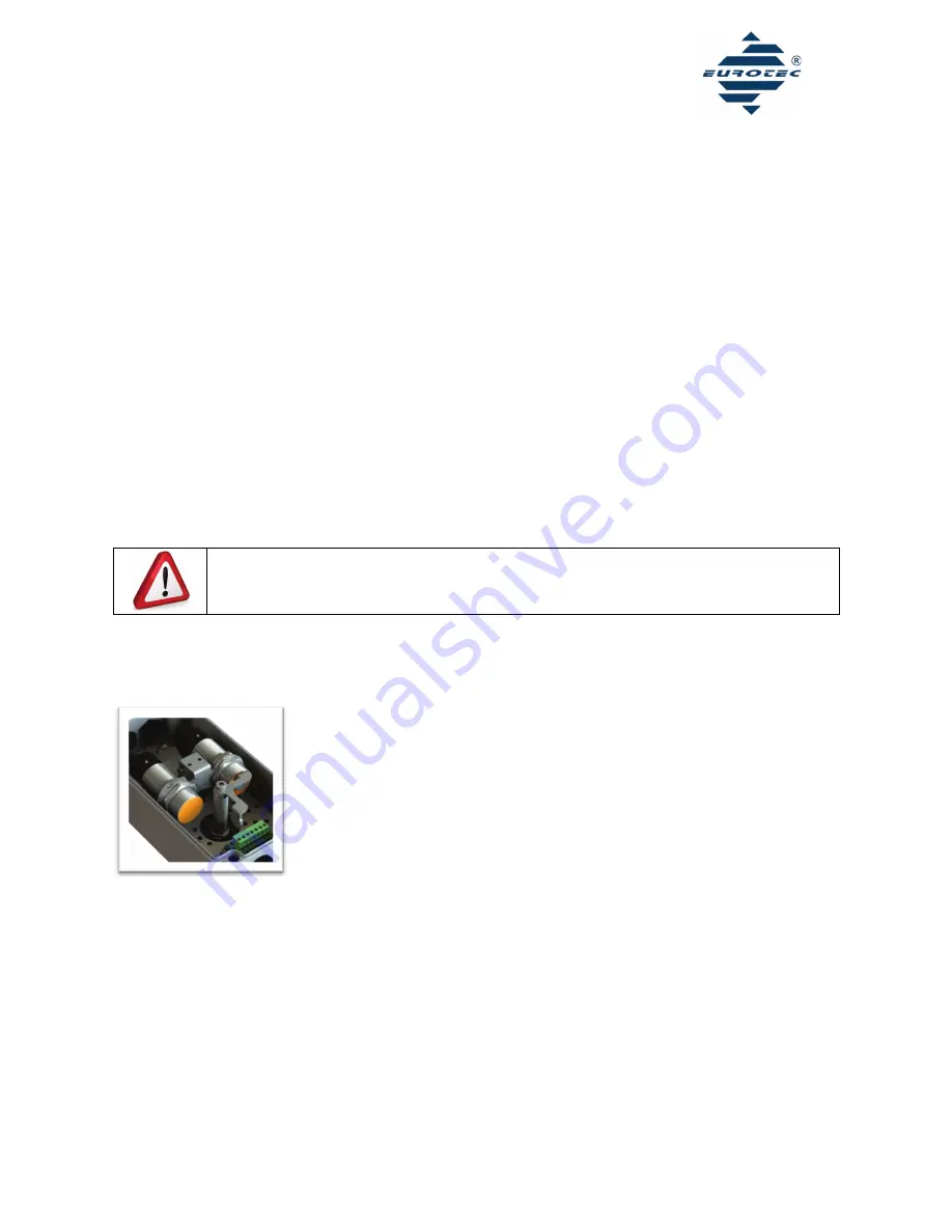
EUROTEC standard terminal block:
Wire cross section: 0,2 - 2,5mm2 (single-wire inflexible) / 0,25 - 2,5mm2 (single-wire flexible or with ferrule)
Stripping length: 7mm
Tightening torque: 0,5 - 0,6 Nm
Abb. 2: Standard terminal block
8.
Dismantling
When dismantling, observe the instructions from chapter 3.
1.
Disconnect the housing from the power supply.
2.
Loosen the 4 cover screws and open the switch box. Do not unscrew them too far so that the screws do remain plugged into the cover.
3.
Disconnect the system cable from the terminal block of the limit switch box.
4.
Loosen the 4 screws that hold the mounting bracket on the actuator and remove the switch box from the actuator.
9.
Setting of the swivel range
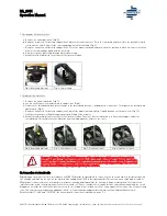
In delivered status the cams are always preset on a swivel range of 0 - 90°. If you need another swivel range, please proceed with the
following steps:

