BA_S011
Operation Manual
EUROTEC Antriebszubehör GmbH | Bildstock 37 | DE-88085 Langenargen | sales@eurotec-shop.com | www.eurotec-shop.com | 19.11.2015 | Seite 4 von 5
1.
Rectangular V3 limit switches
a.
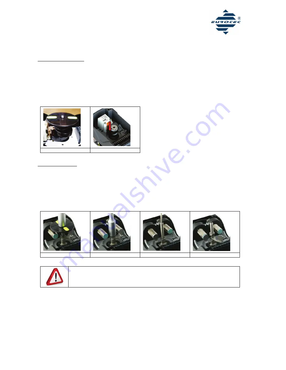
Remove the visual indication. (Fig. 5)
b.
Bring the actuator in the desired end position 1. Adjust the lower cam first. Press the cam down and turn it into the position in which
it actuates the switch. Now let the cam engage again with the toothing. (Fig. 6)
c.
Bring the actuator in the desired end position 2. Press the upper cam down and turn it into the position in which it actuates the switch.
Now let the cam engage again with the toothing.
d.
Finally verify your presetting through repeated switching.
e.
Mount the visual indication to the shaft of the limit switch box.
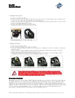
Fig. 3: Removing indicator
Fig. 4: Cam setting
2.
Cylindrical limit switches
f.
Remove the visual indication. (Fig. 7)
g.
Loosen the M6 nut screw and remove the upper cam. (Fig.8)
h.
Unfasten the threaded rod, bring the actuator in the desired end position 1, and adjust the lower cam. Then tighten the threaded rod
again firmly. (Fig. 9)
i.
Bring the actuator in the desired end position 2, adjust the upper cam and tighten it again by means of the nut screw. (Fig. 10)
j.
Finally verify your presetting through repeated switching of the actuator.
k.
Mount the visual indication to the shaft of the limit switch box. Take care that the indication is in line with the upper end of the
threaded rod. This will prevent the indication from touching upon the fixture or the cover.
Fig. 5: Removing indicator
Fig. 6: Loosen nut screw
Fig. 7: Fixation of cam 1
Fig. 8: Fixation of cam 2
Danger of injury. During the switching process of the actuator you might squeeze body parts bet-
ween switch and cam. Stay far enough away from the source of danger when switching the actuator.
Attention, the switch can be damaged by the cams in the event of a wrong presetting. Take care that
the cam does not hit the switch when switching the actuator.
10.
Connection of solenoid coils
Depending on the model, the limit switch boxes of EUROTEC provide the possibility to connect one or two solenoid coils inside the housing.
The suitable switch boxes for one coil are marked with an additional '-MA' in their part number. This version has a cable with a length of
500mm that is connected to the terminal block inside the housing and lead outside the housing through a cable gland. The leads of this
cable have to be wired to the plug connector of the solenoid coil. Please consider the coil manufacturer’s operation manual and the circuit
diagram on or inside the limit switch box cover or on the according technical data sheet. The same applies to the connection of two solenoid
coils. This version is marked with an additional '-2MA' in it’s part number and provides two cables with a length of 500mm each.
With the models “-2KV” and “-2NPT1/2” the solenoid valve connection is optional on poles 7-9.

