BA_S003
Operation Manual
EUROTEC Antriebszubehör GmbH | Bildstock 37 | DE-88085 Langenargen | sales@eurotec-shop.com | www.eurotec-shop.com | 24.04.2018 | Seite 2 von 2
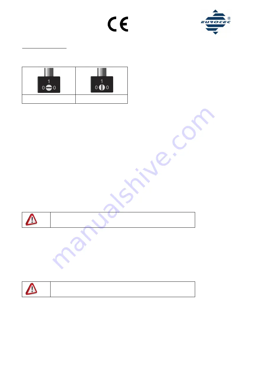
Emergency manual override
Ensure that the emergency manual override in set to the “0” off position. Otherwise the valve cannot be controlled via the coil. It will then
not work. (Images 1+2)
Image 1: “0” off position
Image 2: “1” on position
5.
Dismantling
When dismantling, observe the instructions from chapter 3.
1. Ensure that there is no tension or compressed air in the valve.
2. Disconnect all cables from the valve
3. Loosen the 2 socket screws and remove the valve from your device.
6.
Air supplies
The air supply should always be sourced via connection no. 1.
MF52…:
Connections 3 and 5 are for exhaust air and must never be sealed with air-permeable components. However, we recommend furnishing
connections 3 and 5 with a silencer (SDK ¼”), an exhaust check valve (ERV-G1/4) or an exhaust air restrictor (DRSD ¼”) to prevent dirt from
getting inside the valve and to reduce the noise of the escaping compressed air. Connections 2 and 4 are to control the double acting
pneumatic swivel drive motor or cylinder.
MF32…:
Connection 3 is for exhaust air and must never be sealed with air-permeable components. However, we recommend furnishing connection 3
with a silencer (SDK ¼”), an exhaust check valve (ERV-G1/4) or an exhaust air restrictor (DRSD ¼”) to prevent dirt from getting inside the
valve and to reduce the noise of the escaping compressed air. Connection 2 is to control the single acting pneumatic swivel drive motor or
cylinder.
Complaints on the grounds of dirt in the valve are not the fault of the manufacturer
and therefore not covered by warranty!
7.
Operation
Only operate the valve with clean oiled or non-oiled compressed air with an ISO 8573-1 quality level of 5. Other cleaning methods are not
considered to be suitable. If you use oiled compressed air you should remove this using suitable measures (exhaust). The temperature
increase of the device depends on the means used and on the surface temperature of the valve magnet. Method and ambient temperature
range should be from -20°C to +50°C. For temperatures under 0°C, you must use dry air. Permitted operating pressure: 2 - 10 bar
8.
Maintenance
Regularly check that the device functions flawlessly. At least every 6 months or after a maximum of 5 million switch cycles.
WARNING! There is a risk of injury!
The device, especially the trip coil, can be very hot during operation.
9.
Malfunctions
If a malfunction occurs, check the electric and pneumatic line connections, the supply voltage and the operational pressure. Rectify any
possible faults. If this does not rectify the malfunction, be sure the there is no pressure on the device and disconnect the device from the
power supply voltage. Consult an authorised and trained specialist member of the manufacturer’s staff.


