Getting started with your GEMINI
Issue D
17
Using the USB ports
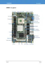
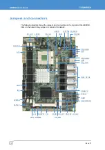
USB ports 1 and 2 are standard USB Type A connectors. USB Ports 3&4 and USB ports
5&6 are provided on a 10-way header (CN_USB1/2) designed to be compatible with PC
expansion brackets that support two USB sockets.
See pages
,
and
for further details.
Using the Ethernet interface
The GEMINI provides four 10/100/1000 Ethernet ports as standard, thus providing
Gigabit Ethernet capability.
Ethernet interfaces are capable of supporting network boot features. Four rear panel RJ-
45 pin connectors provide the Ethernet interface. To support Gigabit Ethernet capabilities,
a cable rated to CAT5e or above with four signals pairs should be used.
Further information on the Ethernet interfaces is available on page
.
Connecting a monitor
Connect the CRT or analogue LCD monitor with DB15 male plug to the onboard DB15
female connector on rear I/O port. You can also use a DVI monitor connected to the DVI-I
connector available on the DVI/SDTV breakout board provided in the kit.
Connecting a television
The GEMINI supports both SDTV and HDTV. You can either use the S-Video or
composite cable supplied to connect to a standard television or use the YPrPb
component cable to connect to a High Definition TV for better resolution performance.
The DVI/SDTV breakout board also provides S-Video and composite interfaces.
Setting up the BIOS
The motherboard uses the Award BIOS for the system configuration. The Award BIOS in
the single board computer is a customized version of the industrial standard BIOS for
IBM PC AT-compatible computers. It supports Intel x86 and compatible CPU architecture
based processors and computers. The BIOS provides critical low-level support for the
system central processing, memory and I/O sub-systems.
The BIOS setup program of the single board computer lets the customers modify the
basic configuration setting. The settings are stored in a dedicated battery-backed
memory, NVRAM, retaining the information when power is turned off. If the battery runs
out of the power, the BIOS settings will be set to the default programmed values.
To activate the CMOS Setup program, press DEL immediately after you turn on the
system. The following message ‘Press DEL to enter SETUP’ should appear in the lower
left hand corner of your screen. When you enter the CMOS Setup Utility, the Main Menu
is displayed. You can use arrow keys to select the required menu, press Enter to accept
the selection and enter the sub-menu.


