Graphics ClientM User Manual
110120-1000A
34
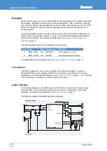
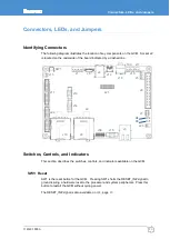
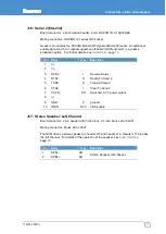
J8: Backlight
Board connector: 7-pin header, 1.25 mm, Molex 53398-0771
Mating connector: Molex 51021-0700
Header J8 includes the power and control signals required by an external LCD backlight
inverter. For a description about the backlight power options, see
. For further details about the control signals, see
Pin
Name
Type
Description
1
BL_VCC
PO
Backlight power output
2
3
GND
P
ground
4
5
BKLT_ON#
OD
Backlight on/off
6
BKLT_PWM
AO
Backlight intensity
7
GND
P
ground
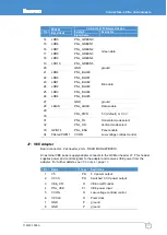
J9: SD/MMC 2
Board connector: SD/MMC socket, 3M SD-RSMT-2-MQ
Mating connector: SD/MMC card
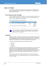
Socket J9 provides SD/MMC 2 for memory and I/O expansion. Shields are tied to
chassis ground. A standard GCM supports 3.3 V cards with a volume production option
for 1.8 V cards. For further details, see
Pin
Name
Type
Description
1
SD2_DAT3
IO
SD/MMC 2 Data
2
SD2_CMD
IO
SD/MMC 2 Command
3
GND
P
ground
4
SD2_PWR
PO
Software-controlled 3.3 V power output
5
SD2_CLK
O
SD/MMC 2 Clock
6
GND
P
ground
7
SD2_DAT0
IO
SD/MMC 2 Data
8
SD2_DAT1
IO
SD/MMC 2 Data
9
SD2_DAT2
IO
SD/MMC 2 Data
10
SD2_CD#
I
SD/MMC 2 Card Detect
11
SD2_WP#
I
SD/MMC 2 Write Protect
Summary of Contents for PXA320
Page 62: ...www eurotech com ...

