EK-MFR/1 Arch.2573
Rev. E of 22/06/2007
Sh. 17 of 35
501-000658/MN
Eurotek s.r.l.
>Save Config
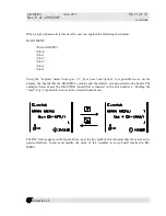
EK-MFR/1 allows to store four configurations system. To save a personal configuration, it is
necessary to enter in the Save Config menu; it is possible to choose on which configuration to store
the personal system settings pressing the “enter” key and using the “modifying variable” keys (par.
2.2, front panel description). The four possible configurations to be used are: Config 0, Config 1,
Config2 and Config3.
>Get Config
The Get Config menu allows to recall one of the four possible configurations stored in the Save
Config menu using the Get from function.
>Miscellaneous
The Miscellaneous menu allows to monitory and control many EK-MFR/1 functions, by the
variables listed below:
>>Volt in 0:
Allows to read a DC voltage (0÷12 VDC) eventually present on the
pin 4 of the auxiliary connector of the EK-PWS/X board.
>> Volt in 1:
Allows to read a DC voltage (0÷12 VDC) eventually present on the
pin 17 of the auxiliary connector of the EK-PWS/X board.
>> Volt out 0:
Allows to set a DC voltage (0÷12 VDC, 10 mA max) at the output of
the auxiliary connector (pin 5) of the EK-PWS/X board.
>>Volt out 1:
Allows to set a DC voltage (0÷12 VDC 10 mA max) at the output of
the auxiliary connector (pin 18) of the EK-PWS/X board.
>>Board Temp: Allows to read the EK-PWS/X board temperature.
>>12V rail:
Allows to monitory the DC voltage (12VDC) generated from the EK-
PWS/X board and supplied to all EK-MFR/1 slots.
>>3.3V rail:
Allows to monitory the DC voltage (3.3VDC) generated from the EK-
PWS/X board, used by the processor and supplied to all EK-MFR/1
slots.
>>Dc rail in
Allows to monitory the eventual external DC voltage that is present on
the auxiliary connector of the EK-PWS/X board.
>>Time to exit:
Allows to set the time when the display is on, afterward the display
will go in stand-by modality, in order to limit the consumption of the
entire machine. It is possible to set the time to exit parameter between
1,10,20 or 30 minute.
>>SCI 2:
Allows to switch on and off the secondary serial interface present on
the auxiliary connector of the EK-PWS/X board.

