EK-MFR/1 Arch.2573
Rev. E of 22/06/2007
Sh. 20 of 35
501-000658/MN
Eurotek s.r.l.
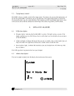
The Slot 4 Viterbi Ber row, indicates that the Viterbi ber variable is out of the limits and an alarm is
present (LED Actual, par. 6.1, LEDs description). Slot 4 Viterbi Ber row is flashing until the
variable is out of the limits.
It is possible that more alarms are simultaneously present; in this case the alarms are showed on the
same row on the display every two seconds. This function allows to have a general information of
the alarms without to explore the menu of every used slot.
7.
ABOUT OPERATING SYSTEM
7.1
Operating system connection.
It is possible to connect the EK-MFR/1 with a terminal unit to use the RS232 interface (to see the
rs232 interface settings in the Appendix C) or the Ethernet 10/100 Base T interface. The connectors,
of these interfaces, are visible in the chapter 3 “rear panel”. The description of the connectors, with
the pins indication, is reported in the EK-PWS/X user’s handbook.
When the EK-MFR/1 is connected and the general switch is turned on (par. 2.2, front panel
description), the insertion of the EK-MFR/1 login is required:
EK-MFR/1 login:
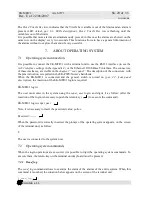
The user must enter in the system using the super_user login, and digits it as follow: (after the
insertion of the login is necessary to push the return key ( ) to execute the command).
EK-MFR/1 login: super_user
Now, it is necessary to insert the password value: pollon
Password: ------
When the password is correctly inserted, the prompt of the operating system appears, on the screen
of the terminal unit, as follow:
$
The user is connected to the system now.
7.2
Operating system commands
When the login operations are executed, it is possible to digit the operating system commands. To
execute them, the return key on the terminal unit keyboard must be pressed.
7.2.1 Read_log
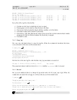
The read_log command allows to examine the status of the alarms of the entire system. When this
command is launched, the situation below appears on the screen of the terminal unit:
$ read_log

