)XQFWLRQ
#
%ORFNV
##
804<
953#
9HFWRU
#
'ULYH
#0#
+$
7968;7
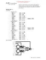
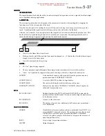
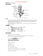
ENCODER SIGN
If the Encoder sign is incorrect the motor will not operate smoothly.
The sign of the encoder can be changed either in hardware by swapping the A
and B channels or by toggling this parameter.
A third way of matching encoder sign to motor direction is to swap any two
motor output phases.
63(('
#
)(('%$&.
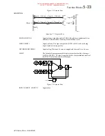
The 620 requires an encoder feedback device tightly coupled to the motor shaft to achieve its high level of
performance. This is because accurate real time measurement of shaft position is used in the vector
calculations. The number of encoder lines is also important to achieve high performance, the higher the number
of lines the greater the speed loop gain. Also as a result of more lines the high frequency ripple in the torque is
also reduced, reducing audible noise.
The number of lines on the encoder is set in the
SETUP PARAMETERS::CALIBRATION
menu. An incorrect
number of lines will prevent the drive from operating smoothly and in some circumstances may cause the drive
to operate in an uncontrolled manner.
$'9$1&('
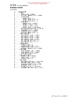
SPEED FBK FILTER
A simple filter function that is applied to speed feedback to reduce ripple
caused by low line count encoders. A value of 0 disables the filter action
and 1.00 is the maximum value. A typical value would be between 0.5 and
0.75, previous releases had a default of 0.5.
NOTE: INCREASING THE FILTER VALUE MAY MAKE THE SPEED
LOOP UNSTABLE.
SPEED DMD FILTER
A simple filter function applied to speed demand to reduce ripple. A value
of 0 disables the filter action and 1.00 is the maximum value.
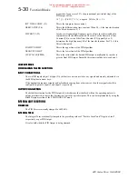
ADAPTIVE THRESHOLD
Level below which the ADAPTIVE P-GAIN is selected
ADAPTIVE P-GAIN
P-Gain used when speed error is less than the adaptive threshold, this may
be used to lessen motor noise in the steady state.
127(6
=
127(6
=
127(6
=
127(6
=
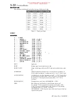
The filter time constant
τ
in milli-seconds can be calculated from the following equation .
=
α
τ
1
1
.
1
e
Log
Where
α
is the value of SPD FBK FILTER or SPD DMD FILTER. A value of 0.5 equates to a filter time of
1,6mS, 0.8 to 4.9mS and 0.9 to 10.4mS.
32:(5
#
/266
#
&21752/
127(6
=
127(6
=
127(6
=
127(6
=
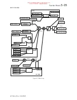
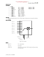
The power loss control on the 620 works if enabled, by continually comparing the actual value of DC-Link
volts to a threshold. If the actual value of the DC-Link falls below this
TRIP THRESHOLD
then the drive
attempts to pump-up the DC-Link by decelerating the load, thus recovering its stored kinetic energy. Once the
drive reaches zero speed or a time out occurs then a POWER LOSS alarm is triggered. If the power supply is
resumed before the load has reached zero speed then the load is ramped back up to the actual demanded speed.
If there is not enough kinetic energy in the load or the deceleration rate is set too long then an under voltage trip
will be trigged. Over Voltages may also occur if the deceleration rate is too fast and there is insufficient
dynamic braking fitted.
This manual was downloaded on www.sdsdrives.com
+44 (0)117 938 1800 - info@sdsdrives.com


