70;##
6HWWLQJ
0
XS
#
DQG
#
&RPPLVVLRQLQJ
953#
9HFWRU
#
'ULYH
#0#
+$
7968;7
6HWXS
#
6WHS
#7####
3RZHU
#
2Q
Once all the preceding steps are completed and understood, the supply fuses or circuit breaker may be replaced
and power applied to the drive.
Setting up the drive consists of:
Setting up basic motor parameters via the MMI.
Running Autotune to set up magnetising current and slip.
Tuning the speed loop for the particular application.
,QLWLDO
#
6HWXS
,QLWLDO
#
6HWXS
,QLWLDO
#
6HWXS
,QLWLDO
#
6HWXS
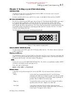
When the 620 Vector drive is switched on, the HEALTH LED should light. The remaining 3 LEDs should be off
and the power-up message should appear on the MMI display as follows:
1. Press
M
M
. The display will show
‘MENU LEVEL / DIAGNOSTICS’
. Pressing the
and
buttons
will enable you to move around the top level menu. Press
until the display shows
CONFIGURE DRIVE
(if
you miss
CONFIGURE DRIVE
or any other menu item, either use the
button to get back or keep pressing
until
CONFIGURE DRIVE
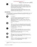
is displayed again). You will be navigating the Initial Setup menus shown at
the extreme left of Fig 4.3.
2. Ensure that the
‘CONFIGURE DRIVE’
menu is selected on the display. Press
M
to enter this menu. When
you enter the menu, the first parameter to appear on the display will be
ENCODER LINES
. Other parameters
may be selected by means of the
and
buttons. Locate
ENCODER LINES
and press
M
to select this
parameter. Use the
and
buttons to enter the number of lines on the encoder. When you have entered the
correct number of encoder lines, press
E
to return to the previous level where the remaining parameters may be
accessed.
3. Press to select
MAX SPEED RPM
and then press
M
. This entry sets the maximum rotation speed for the
process, and can be up to 9 times the motor base speed printed on the nameplate if required. (This speed will be
the 100% speed referred to elsewhere in the MMI). Use the
and
buttons to set the
MAX SPEED RPM
parameter to the required figure. Press
E
.
It is important at this stage to set
MAX SPEED RPM
to the highest value that you are likely to be using. This is
because the autotune will only set up the magnetising current values up to this speed. If at a later stage you wish
to run the motor faster then it will be necessary to re-run the autotune. To avoid this inconvenience, set up
MAX
SPEED RPM
to a high value now, and reduce it after autotune if required. The maximum motor speed should
not of course be exceeded.
4. Press to select
BASE FREQUENCY
and then press
M
. Read the motor power supply frequency from the
motor nameplate (typically 50Hz or 60 Hz) and use the
and
buttons to set the
BASE FREQUENCY
parameter to the same figure. Press
E
.
5. Press to select
MOTOR VOLTAGE
and then press
M
. Read the motor power supply voltage from the motor
nameplate and use the
and
buttons to set the
MOTOR VOLTAGE
parameter to the same figure. Press
E
.
6. Press to select
MOTOR RATING RMS
and then press
M
. Read the motor full-load current from the motor
nameplate and use the
and
buttons to set the
MOTOR RATING RMS
parameter to the same figure. Press
E
.
7. Press to select
NO.OF POLES
and then press
M
. Read the number of poles from the motor nameplate.
This number must be divisible by 2, e.g. 2, 4, 6, 8 etc. or an error will be generated later. Use the
and
buttons to set the
NO.OF POLES
parameter. Press
E
.
8. Press to select
NAMEPLATE RPM
and then press
M
. Read the base speed from the motor nameplate, and
use the
and
buttons to set the
NAMEPLATE RPM
parameter to the specified figure. Press
E
. It is
important to enter this value exactly as it appears on the nameplate. For example, if it appears on the nameplate
as 1450rpm, DO NOT round it up to 1500rpm.
620 VECTOR DRIVE
TYPE X CHASSIS
This manual was downloaded on www.sdsdrives.com
+44 (0)117 938 1800 - info@sdsdrives.com


