26
Product-manual Model: 635/DER u. 635/K DER
07-01-05-06-E-V1002.doc
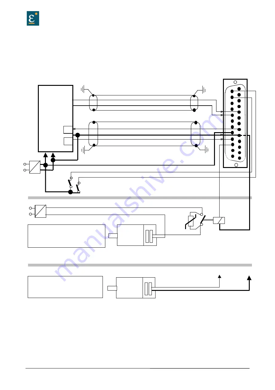
Signal connections
Control signal plug X10
SUB D25 socket
Connection example
model: SUB D 25
signal plug für X10
1
2
3
4
5
6
7
8
9
10
11
12
13
14
15
16
17
18
19
20
21
22
23
24
25
regulator side
spread out
spread out
SPS
output ready
0V-reference point, I/O-supply
input active
+/- 10V
+24 V, I/O-supply
24V
+
-
0V
Mecanical
Limit schwitsches
1)
1)
~
=
L1
N
2)
V1: Varistor; e.g. Siemens Q69X3431, 38V DC
K1: Couple-relais min. 2A,/60VDC PELV Isolation
~
=
L1
N
Option: brake
Eurotherm
AC-Servomotors
3 ~
V1
K1
+24V (Br)
0V (Br)
AC-Servomotors
3 ~
X10.23
X10.9
Brake-connection variants A
:
when Isolation - Type of break-isolation is
basic (not PELV). The PELC - isolation of
control - cirquits is uneffected
Bremsenanschluss Variante B :
wehn isolation - type of brake - installation is
PELV
PELV-
Isolation
2)
Supply may be used for multiple brakes
Option: brake
1) Security- and supervising logic, to be programmed by user !
2)
IMPORTANT:
The Power-Supply for the Motor-Brake has to be adapted to the type of Brake. Voltage-Drops
caused by long cables also may effect malfunctions of the Brake
Summary of Contents for 635
Page 63: ...Product manual Model 635 DER u 635 K DER 07 01 05 06 E V1002 doc 63 10 Block circuit diagram ...
Page 72: ...72 Product manual Model 635 DER u 635 K DER 07 01 05 06 E V1002 doc 14 Certificates ...
Page 73: ...Product manual Model 635 DER u 635 K DER 07 01 05 06 E V1002 doc 73 Certificates ...
Page 74: ...74 Product manual Model 635 DER u 635 K DER 07 01 05 06 E V1002 doc Certificates ...
Page 75: ...Product manual Model 635 DER u 635 K DER 07 01 05 06 E V1002 doc 75 Certificates ...
Page 77: ...Product manual Model 635 DER u 635 K DER 07 01 05 06 E V1002 doc 77 16 Notes ...


