3200 Series
106 Part No HA028651 Issue 7.0 Apr-09
17.7
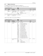
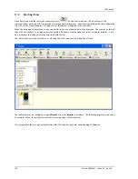
To Customise Messages
The message which scrolls across the controller display during normal operation may be customised.
17.7.1
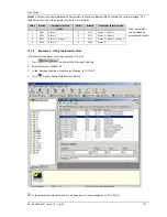
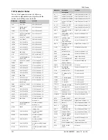
Example 1: Using the Wizard
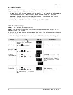
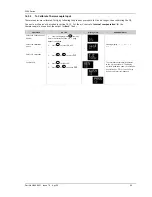
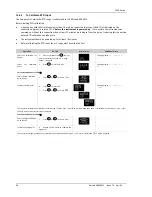
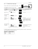
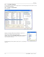
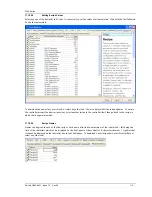
Select the ‘Messages’ tab.
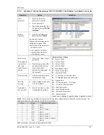
Display the message ‘OUT OF CONTROL’ if both Alarm 1 and Alarm 2 are active.
Operation
Action
Indication
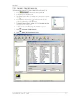
Add a
parameter
Click where the parameter is
required
Select ‘Insert’
Choose the parameter from
the pop up box eg ‘STATUS
InstStatus’
The parameter may be
edited, removed or its
position changed by selecting
the relevant tab
Set the
Operator
From the ‘Operator:’ drop
down box select ‘Mask’ – see
Note 1.
Alternatively a message may
be configured to appear if
the enumeration of the
parameter:-
= equals the ‘Value’
<> is greater or less than the
‘Value’
> is greater than the ‘Value’
< is less than the ‘Value’
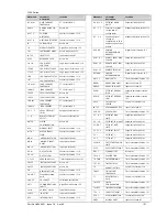
Set the
value
The bitmap
list is given
here and in
the Digital
Comms
chapter
1.
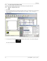
Click in the ‘Value’ box
and press enter
2.
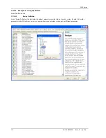
From the pop up box
either tick the bit field
values or type in the
decimal equivalent in
‘New Value’. In this
example 3 (alarm 1 +
alarm 2).
Set the
priority
3.
From the drop down
select Low Medium or
High
Enter the
message
4.
In the message section
enter OUT OF CONTROL
Download
to the
controller
5.
Press <Back, Next> or
Close to download the
settings
Instrument Status - Bitmap
B0 – Alarm 1 Status
B1 – Alarm 2 Status
B2 – Alarm 3 Status
B3 – Alarm 4 Status
B4 – Auto/Manual Status
B5 – Sensor Break Status
B6 – Loop Break Status
B7 – CT Low load current alarm status
B8 – CT High leakage current alarm status
B9 – Program End
B10 – PV Over-range (by > 5% of span)
B11 – CT Overcurrent alarm status
B12 – New Alarm Status
B13 – Timer/Ramp Running
B14 – Remote Fail, New Alarm
B15 – Auto-tune Status
In each case, a setting of 1 signifies ‘Active’, 0 signifies ‘Inactive’.


