3200 Series
Part No HA028651 Issue 7.0 Apr-09 9
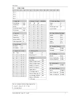
2.2
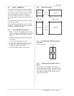
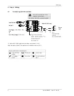
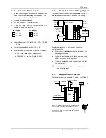
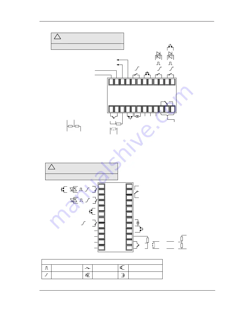
Terminal Layout 32h8 Controllers
2.3
Terminal Layout 3208 and 3204 Controllers
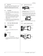
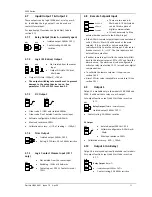
Key to symbols used in wiring diagrams
Logic (SSR drive) output
Relay output
Contact input
mA analogue output
Triac output
Current transformer input
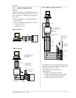
Digital Communications
EIA232 or EIA485
Or
Remote Setpoint IP
See section 2.8
Output 4 (AA Relay)
Line Supply
100 to 240Vac 48 to 62 Hz
OR
Low Voltage Supply
20 - 29Vac/dc
Input/Output 1
CT input
Digital input A
AA
AB
AC
HD
HE
HF
CT
C
LA
VI
V+
V-
1A
1B
2A
2B
LB
LC
3A
3B
3C
3D
L
N
COM
A(+)
B(-)
-
+
T/C
+
mV
-
PV Input
Pt100
2.49
Ω
mA
-
+
+
-
+
24V
-
Output 2
Digital Input B
Output 3
24V Transducer Supply
10V
Potential divider
module
Part No
SUB21/IV10
-
+
10V
Input
+ +
- -
+ +
- -
- + - +
- + - +
- +
C NO C NO
Line Supply 100 to 240Vac 48 to
62
Hz
OR
Low Voltage Supply 24Vac/dc
10V Potential divider
module
Part No SUB21/IV10
-
+
10V Input
Output
3
24V Transmitter Supply
AA Relay (OP4)
B(-) A(+) COM
Digital Comms
Or
Remote
Setpoint IP
See section 2.8
-
+
T/C
Sensor
Input
Pt100
V- V+ VI LA C CT HF HE HD AC AB AA
N L 3D 3C 3B 3A LC LB 2B 2A 1B 1A
2.49
Ω
mA/mV
+
-
-
+
32h8 Controller
Dig in A
CT input
Output
2
Input/
Output 1
Dig
in B
C NO
!
Ensure that you have the correct
supply for your indicator
Check order code of the controller supplied
!
Ensure that you have the correct
supply for your indicator
Check order code of the controller supplied

