3200 Series
120 Part No HA028651 Issue 7.0 Apr-09
19.
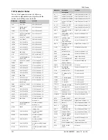
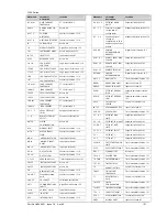
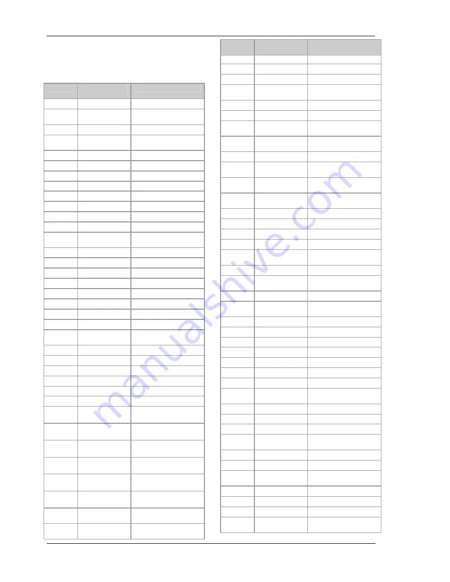
Parameter Index
This is a list of parameters used in 3200 series
controllers in alphabetical order together with the
section in which they are to be found.
Mnemonic
Parameter
Description
Location
1.ID
I/O 1 TYPE
IO1 List Section 9.1
1.D.IN DIGITAL
INPUT
FUNCTION
IO1 List Section 9.1
1.FUNC
I/O 1 FUNCTION
IO1 List Section 9.1
1.PLS
OUTPUT 1 MINIMUM
PULSE TIME
IO1 List Section 9.1
1.RNG
DC OUTPUT RANGE
IO1 List Section 9.1.1
1.SENS
I/O 1 SENSE
IO1 List Section 9.1
1.SRC.A
I/O 1 SOURCE A
IO1 List Section 9.1
1.SRC.B
I/O 1 SOURCE B
IO1 List Section 9.1
1.SRC.C
I/O 1 SOURCE C
IO1 List Section 9.1
1.SRC.D
I/O 1 SOURCE D
IO1 List Section 9.1
2.FUNC
FUNCTION
OP2 List Section 9.1.7
2 . I D
OUTPUT 2 TYPE
OP2 List Section 9.1.7
2.PLS OUTPUT
MINIMUM
PULSE TIME
OP2 List Section 9.1.7
2 . R N G
DC OUTPUT RANGE
OP2 List Section 9.1.7
2.SENS
SENSE
OP2 List Section 9.1.7
2.SRC.A
I/O 2 SOURCE A
OP2 List Section 9.1.7
2.SRC.B
I/O 2 SOURCE B
OP2 List Section 9.1.7
2.SRC.C
I/O 2 SOURCE C
OP2 List Section 9.1.7
2.SRC.D
I/O 2 SOURCE D
OP2 List Section 9.1.7
3.FUNC
FUNCTION
OP3 List Section 9.1.8
3 . I D
OUTPUT 3 TYPE
OP3 List Section 9.1.8
3.PLS OUTPUT
MINIMUM
PULSE TIME
OP3 List Section 9.1.8
3.RNG
DC OUTPUT RANGE
OP3 List Section 9.1.8
3.SENS
SENSE
OP3 List Section 9.1.8
3.SRC.A
I/O 3 SOURCE A
OP3 List Section 9.1.8
3.SRC.B
I/O 3 SOURCE B
OP3 List Section 9.1.8
3.SRC.C
I/O 3 SOURCE C
OP3 List Section 9.1.8
3.SRC.D
I/O 3 SOURCE D
OP3 List Section 9.1.8
4.FUNC
FUNCTION
AA Relay List (OP4)
Section 9.1.9
4.PLS OUTPUT
MINIMUM
PULSE TIME
AA Relay List (OP4)
Section 9.1.9
4.SENS
SENSE
AA Relay List (OP4)
Section 9.1.9
4.SRC.A
I/O 4 SOURCE A
AA Relay List (OP4)
Section 9.1.9
4.SRC.B
I/O 4 SOURCE B
AA Relay List (OP4)
Section 9.1.9
4.SRC.C
I/O 4 SOURCE C
AA Relay List (OP4)
Section 9.1.9
4.SRC.D
I/O 4 SOURCE D
AA Relay List (OP4) Section
9.1.9
4.TYPE
OUTPUT 4 TYPE
AA Relay List (OP4) Section
9.1.9
Mnemonic
Parameter
Description
Location
A 1 . - - -
ALARM 1 SETPOINT
Alarm Parameters Section 12.3
A1.BLK
ALARM 1 BLOCKING
Alarm Parameters Section 12.3
A1.HYS
ALARM 1 HYSTERESIS
Alarm Parameters Section 12.3
A1.LAT
ALARM 1 LATCHING
TYPE
Alarm Parameters Section 12.3
A 1 . S T S
ALARM 1 OUTPUT
Alarm Parameters Section 12.3
A1.TYP
ALARM 1 TYPE
Alarm Parameters Section 12.3
A D D R COMMUNICATIONS
ADDRESS
Digital Comms Section 15.2
A - M
LOOP MODE - AUTO
MANUAL OFF
Control List Section 11.10
A T U N E
INTEGRAL TIME
Control List Section 11.10
A T . R 2 G AUTO-TUNE
CONFIGURES R2G
Control List Section 11.10
B A U D COMMUNICATIONS
BAUD RATE
Digital Comms Section 15.2
C . A D J CALIBRATION
ADJUST
Calibration Section 16.4
C B H I
CUTBACK LOW
Control List Section 11.10
C B L O
CUTBACK HIGH
Control List Section 11.10
CJ.TYP CJC
TYPE
Input List Section 8.1
CJC.IN CJC
TEMPERATURE
Input List Section 8.1
COLD COLD
START
ENABLE/ DISABLE
Access List Section 6.4
CONF.P
CONFIG PASSCODE
Access List
C O O L . T NON
LINEAR
COOLING TYPE
Control List Section 11.10
CT.ID
MODULE TYPE
CT List Section 9.2
CT.LAT
CT ALARM LATCH
TYPE
CT List Section 9.2
CT.MTR
CT METER RANGE
CT List Section 9.2
CT.RNG
CT RANGE
CT List Section 9.2
CT.SRC CT
SOURCE
CT List Section 9.2
C T R L . A
CONTROL ACTION
Control List Section 11.10
C T R L . C
COOLING TYPE
Control List Section 11.10
C T R L . H
HEATING TYPE
Control List Section 11.10
C Y C L E PROGRAM
CYCLE Timer
Parameters Section 13.1
D . B A N D
CHANNEL 2 DEAD
BAND
Control List Section 11.10
DEC.P DISPLAY
POINTS Input List Section 8.1
D E L A Y
RX/TX DELAY TIME
Digital Comms Section 15.2
D W E L . 1
DWELL 1
Timer Parameters Section 13.1
D W E L L SET
TIMER
DURATION
Timer Parameters Section 13.1
E N T . T
TIMER END TYPE
Timer Parameters Section 13.1
E V E N T
EVENT OUTPUTS
Timer Parameters Section 13.1
F . M O D FORCED
MANUAL
OUTPUT MODE
Control List Section 11.10
F . O P
FORCED OUTPUT
Control List Section 11.10
FILT.T
FILTER TIME
Input List Section 8.1
GO START
CALIBRATION
Calibration Section 16.4
GOTO SELECT
ACCESS
LEVEL
Access List


