3200 Series
12 Part No HA028651 Issue 7.0 Apr-09
2.11
General Note About Relays and
Inductive Loads
High voltage transients may occur when switching
inductive loads such as some contactors or solenoid
valves. Through the internal contacts, these transients
may introduce disturbances which could affect the
performance of the instrument.
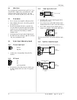
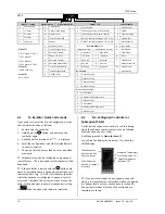
For this type of load it is recommended that a ‘snubber’
is connected across the normally open contact of the
relay switching the load. The snubber recommended
consists of a series connected resistor/capacitor (typically
15nF/100
Ω
). A snubber will also prolong the life of the
relay contacts.
A snubber should also be connected across the output
terminal of a triac output to prevent false triggering
under line transient conditions.
WARNING
When the relay contact is open or it is connected to
a high impedance load, the snubber passes a current
(typically 0.6mA at 110Vac and 1.2mA at 240Vac).
You must ensure that this current will not hold on
low power electrical loads. If the load is of this type
the snubber should not be connected.
2.12
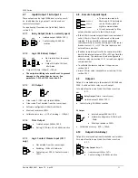
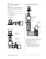
Digital Inputs A & B
Digital input A is an optional input in all 3200 series
controllers
.
Digital input B is always fitted in models
3208, 32h8 and 3204, but is not available in 3216.
•
Not isolated from the current transformer input or
the sensor input
•
Switching: 12Vdc at 40mA max
•
Contact open > 500
Ω
. Contact closed < 200
Ω
•
Input functions: Please refer to the list in the quick
codes.
☺
If EIA232 digital communications is fitted (3216
only), Digital Input A is not available.
2.13
Current Transformer
The current transformer input is an optional input in all
3200 series controllers.
☺
If EIA232 digital communications is fitted (3216
only), Current Transformer Input is not available.
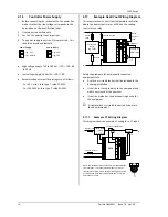
It can be connected to monitor the rms current in an
electrical load and to provide load diagnostics. The
following fault conditions can be detected: SSR (solid
state relay) short circuit, heater open circuit and partial
load failure. These faults are displayed as alarm
messages on the controller front panel.
Note: C terminal is common to both the CT input and
Digital input A. They are, therefore, not isolated from
each other or the PV input.
•
CT input current: 0-50mA rms (sine wave, calibrated)
50/60Hz
•
A burden resistor, value 10
Ω
, is fitted inside the
controller.
•
It is recommended that the current
transformer is fitted with a voltage
limiting device to prevent high voltage
transients if the controller is unplugged.
For example, two back to back zener diodes. The
zener voltage should be between 3 and 10V, rated
at 50mA.
•
CT input resolution: 0.1A for scale up to 10A, 1A for
scale 11 to 100A
•
CT input accuracy: +4% of reading.
2.14
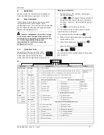
Transmitter Power Supply
The Transmitter Supply is not available in the Model
3216. It is fitted as standard in the Models 3208, 32h8
and 3204.
•
Isolated output 240Vac CAT II
•
Output: 24Vdc, +/- 10%. 28mA max.
•
inside the controller
Dig in A
C
LA
Dig in B
LB
LC
CT Input
CT
C
24Vdc
Transmitter Supply
3C
3D

