3200 Series
18 Part No HA028651 Issue 7.0 Apr-09
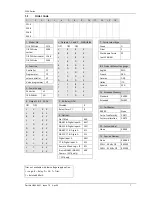
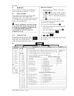
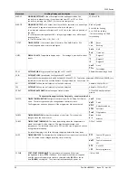
SET 2
Input CT Scaling
Digital Input A
Digital Input B (2)
Output 3 (2)
Lower Display
X
Unconfigured
X Unconfigured
X
Unconfigured
T
Setpoint
(std)
1
10 Amps
W
Alarm acknowledge
H
PID heating or motor valve open (3)
P
Output
2
25 Amps
M
Manual select
C
PID cooling or motor valve close (3)
R
Time remaining
5
50 Amps
R
Timer/Program Run
J
ON/OFF heating (not shown if VC or VP)
E
Elapsed time
6
100 Amps
L
Keylock
K
ON/OFF cooling (not shown if VC or VP)
1
Alarm setpoint
P
Setpoint 2 select
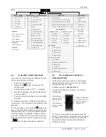
Alarm Outputs (1)
A
Load
Amps
T
Timer/Program reset
Energised in alarm
De-energised in alarm
D Dwell/Ramp
U
Remote SP enable
0 High
alarm 5 High
alarm
Time/Target
V
Recipe 2/1 select
1
Low alarm
6
Low alarm
N
None
A
Remote UP button
2
Dev High
7
Dev High
C
Setpoint with
Note (1)
OP1 = alarm 1 (I/O1)
OP2 = alarm 2
OP3 = alarm 3
OP4 = alarm 4 (AA)
B
Remote DOWN button
3
Dev Low
8
Dev Low
Output meter (2)
G
Timer/Prog Run/Reset
4
Dev Band
9
Dev Band
M
Setpoint with
Note (2)
3208 & 3204 only
I Timer/Program
Hold
DC outputs
Ammeter
(2)
Q
Standby select
H
4-20mA heating
Note (3)
VP, VC only
C
4-20mA
cooling
J
0-20mA heating
K 0-20mA
cooling
Retransmission output
D 4-20
Setpoint
E
4-20 Measured Temperature
F 4-20mA
output
N 0-20
Setpoint
Y
0-20 Measured Temperature
Z 0-20mA
output
4.2
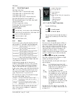
To Re-Enter Quick Code mode
If you need to re-enter the ‘Quick Configuration’ mode
this can always be done as follows:-
1.
Power down the controller
2.
Hold down the
button, and power up the
controller again.
3.
Keep the button pressed until
code
is displayed.
4.
Enter the configuration code (this is defaulted to 4
in a new controller)
5.
The quick start codes may then be set as described
previously
☺
Parameters may also be configured using a deeper
level of access. This is described in later chapters of this
handbook.
☺
If the controller is started with the
button held
down, as described above, and the quick start codes are
shown with dots (e.g. J.C.X.X.X), this indicates that the
controller has been re-configured in a deeper level of
access and, therefore, the quick start codes may not be
valid. If the quick start codes are accepted by scrolling
to
then the quick start codes are reinstated.
4.3
Pre-Configured Controller or
Subsequent Starts
A brief start up sequence consists of a self test during
which the software version number is shown followed
briefly by the quick start codes.
It will then proceed to
Operator Level 1
..
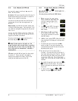
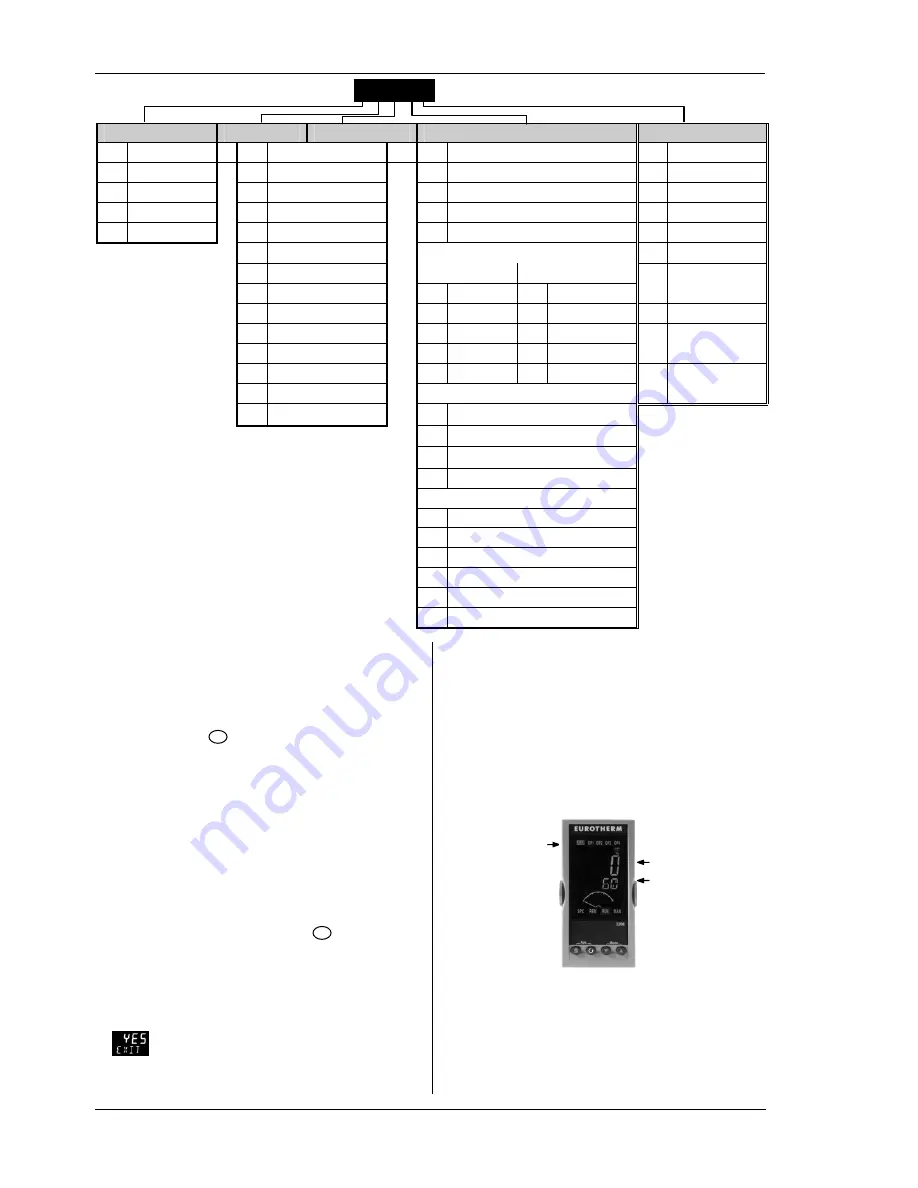
You will see the display shown below. It is called the
HOME display.
☺
If the quick start codes do not appear during this
start up, it means that the controller has been configured
in a deeper level of access, see the note in section 4.2.
The quick start codes may then not be valid and are
therefore not shown.
1 WRDT
Measured Temperature
(or Process Value ‘PV’)
Target Temperature
(Setpoint ‘SP’)
The ALM beacon
will show red if an
alarm is present.
The OP4 beacon
will be on if output
4 is active


