3200 Series
42 Part No HA028651 Issue 7.0 Apr-09
9.1
Input/Output Parameters
9.1.1
Input/Output 1 List (IO-1)
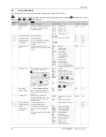
May be configured as relay, logic or DC output or to accept a digital input from external switch contacts. Connections are
made to terminals 1A and 1B. OP1 beacon is operated from the IO-1 channel when it is configured as an output.
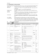
INPUT/OUTPUT LIST 1 ‘
I O -1
’
Name
Scrolling Display
Parameter Description
Value
Default
Access Level
none
No input or output fitted
dC.OP
DC output (see note 1)
ReLy
Relay output
L.IO
Logic Input/Output
1..i d
I/O 1 TYPE
I/O channel 1 hardware
type defined by the
hardware fitted
SSR
Triac output
As
ordered
Read only
none
Disabled. If disabled no further
parameters are shown
d.out
Digital output
UP
Valve open codes VC and VP only
dwn
Valve close codes VC and VP only
Heat
Heat output
CooL
Cool output
d.in
Digital input if ‘
1.i d
’ = ‘
L.IO
HEAt
Conf
w.SP
Working setpoint re-transmission
PV
Process variable re-transmission
1.FUNC
I/O 1 FUNCTION
I/O channel function.
If the instrument is
ordered as valve
positioner (codes VC or
VP), only options available
are ,
none
,
d.out
,
UP
,
or
dwn
Note: If output 1 is set
to
Up
ensure the other
valve position output is
set to
dwn
and vice
versa
OP
Output power demand re-
transmission
Shown if I/O 1 TYPE =
dc.OP
Retransmission
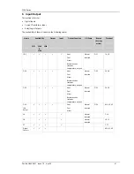
1.SRC.A
I/O 1 SOURCE A
none
No event connected to the output
AL1
Alarm 1
1.SRC.B
I/O 1 SOURCE B
AL2
Alarm 2
AL3
Alarm 3
1.SRC.C
I/O 1 SOURCE C
AL4
Alarm4
ALL.A
All alarms
nw.AL
Any new alarm
Ct.AL
CT alarm, load, leak & overcurrent
Lbr
Loop break alarm
Sbr
Sensor break alarm
t.End
Timer end status
t.run
Timer run status
mAn
Manual status
rmt.F
Remote fail - see section 9.1.2
Pwr.f
Power fail
1.SRC.D
I/O 1 SOURCE D
These parameters only
appear when the channel
function is a Digital
output,
i.e. 1.FUNC =
d.out
Selects an event status to
be connected to the
output channel.
The output status is the
result of an OR of Src A,
Src B, Src C, and Src D
Up to four events can,
therefore, operate the
output
See section 9.1.4
prg.e
Programmer event. See also section
13.2.3
none
Conf
none
Input not used
Ac.AL
Alarm acknowledge
SP2
Setpoint 2 select
Loc.b
Front keypad disable (keylock)
t.res
Timer/programmer reset
t.run
Timer/programmer run
t.rrS
Timer/programmer run/reset. Make
to run, break to reset
t.HLd
Timer/programmer hold
Man
Manual status
Sby
Standby mode. In this mode control
outputs go to zero demand
rmt
Remote digital setpoint select
rec
Recipe select through IO1 digital
input
UP
Remote key ‘Up’
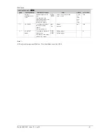
1 . D . I N
DIGITAL INPUT
FUNCTION
This parameter is only
applicable to I/O 1 and
only appears if the
channel function is a
Digital IP
i.e. 1.FUNC =
d.in
Only one function may be
activated by a physical
input
dwn
Remote key ‘Down’
Ac.AL
Conf


