background image

3200 Series 


Part No HA028651    Issue 7.0    Apr-09                                                                                                                                          53 

11.2.2


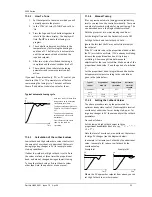
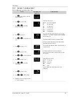
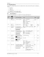
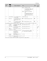
How To Tune 

1.


Set the setpoint to the value at which you will 

normally operate the process.  

2.


In the ‘CTRL’ list, select ‘ATUNE’ and set it to 

‘On’.  

3.


Press the Page and Scroll buttons together to 

return to the Home display.  The display will 

flash ‘

Tune

’ to indicate that tuning is in 

progress.  

4.


The controller induces an oscillation in the 

temperature by first turning the heating on, 

and then off.  The first cycle is not complete 

until the measured value has reached the 

required setpoint.  

5.


After two cycles of oscillation the tuning is 

completed and the tuner switches itself off.  

6.


The controller then calculates the tuning 

parameters and resumes normal control 

action.  

If you want ‘Proportional only’, ‘PD’, or ‘PI’ control, you 

should set the ‘TI’ or ‘TD’ parameters to off before 

commencing the tuning cycle.  The tuner will leave 

them off and will not calculate a value for them. 

 
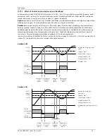
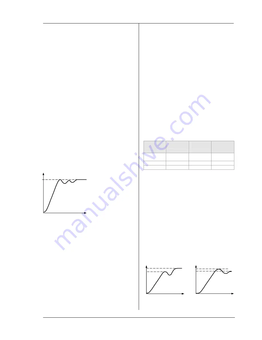
Typical automatic tuning cycle 


11.2.3


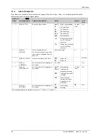
Calculation of the cutback values 

Low cutback

 and 

High cutback

 are values that restrict 

the amount of overshoot, or undershoot, that occurs 

during large step changes in PV (for example, under 

start-up conditions). 
If either low cutback, or high cutback, is set to ‘Auto’ 

the values are fixed at three times the proportional 

band, and are not changed during automatic tuning. 
To tune the cutback values, first set them to values 

other than Auto, then perform a tune as usual. 

11.2.4


Manual Tuning 

If for any reason automatic tuning gives unsatisfactory 

results, you can tune the controller manually.  There are 

a number of standard methods for manual tuning.  The 

one described here is the Ziegler-Nichols method. 
With the process at its normal running conditions: 
Set the Integral Time and the Derivative Time to OFF. 
Set High Cutback and Low Cutback to ‘Auto’. 
Ignore the fact that the PV may not settle precisely at 

the setpoint. 
If the PV is stable, reduce the proportional band so that 

the PV just starts to oscillate.  If PV is already oscillating, 

increase the proportional band until it just stops 

oscillating.  Allow enough time between each 

adjustment for the loop to stabilise.  Make a note of the 

proportional band value ‘P’ and the period of oscillation 

‘T’. 
Set the proportional band, integral time and derivative 

time parameter values according to the calculations 

given in the table below:- 


Type of 

control 

Proportional 

band (P) 

Integral time 

(I) seconds 

Derivative 

time (D) 

seconds 

Proportional 

only  

2xB OFF OFF 

P + I  

2.2xB 

0.8xT 

OFF 

P + I + D 

1.7xB 

0.5xT 

0.12xT 

11.2.5


Setting the Cutback Values 

The above procedure sets up the parameters for 

optimum steady state control.  If unacceptable levels of 

overshoot or undershoot occur during start-up, or for 

large step changes in PV, then manually set the cutback 

parameters.  
Proceed as follows: 
Set the low and high cutback values to three 

proportional bandwidths (that is to say, 

C B . H I

 = 

C B . LO


= 3 x 

P B

). 

Note the level of overshoot, or undershoot, that occurs 

for large PV changes (see the diagrams below). 
In example (a) increase Low Cutback by the undershoot 

value.  In example (b) reduce Low Cutback by the 

overshoot value. 
Example 

(a) 

  Example 

(b) 


Where the PV approaches setpoint from above, you can 

set High Cutback in a similar manner. 

Time 

Setpoint 

PV 

Auto-tune starts 1 minute after 
being turned on to determine 
steady state conditions. 
Tuning normally takes place at a 
PV which has a value of setpoint 
x 0.7.   
The power is automatically 
turned on and off to cause 
oscillations. 
From the results the values 
shown in the table are 
calculated 

U


S


Time 

PV 

U


S


Time 

PV 

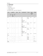
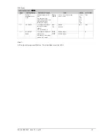
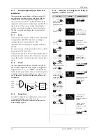
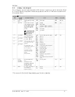
Summary of Contents for 3100

Page 1: ...3100 3200 PID Temperature Controllers Engineering Manual e E U R O T H E R M invensys ...

Page 2: ...he equipment to which the document relates without the prior written permission of Eurotherm Limited Eurotherm Limited pursues a policy of continuous development and product improvement The speci fications in this document may therefore be changed without notice The information in this document is given in good faith but is intended for guidance only Eurotherm Limited will accept no responsibility...

Page 3: ...ut 2 11 2 7 1 Relay Output Form A normally open 11 2 7 2 Logic SSR drive Output 11 2 7 3 DC Output 11 2 7 4 Triac Output 11 2 7 5 Logic Contact Closure Input I O 1 only 11 2 8 Remote Setpoint Input 11 2 9 Output 3 11 2 10 Output 4 AA Relay 11 2 11 General Note About Relays and Inductive Loads 12 2 12 Digital Inputs A B 12 2 13 Current Transformer 12 2 14 Transmitter Power Supply 12 2 15 Digital Co...

Page 4: ... 39 8 2 PV Offset 40 8 2 1 Example To Apply an Offset 40 8 3 PV Input Scaling 40 8 3 1 Example To Scale a Linear Input 40 9 Input Output 41 9 1 Input Output Parameters 42 9 1 1 Input Output 1 List IO 1 42 9 1 2 Remote Digital Setpoint Select and Remote Fail 44 9 1 3 Sense 44 9 1 4 Source 44 9 1 5 Power Fail 44 9 1 6 Example To Configure IO 1 Relay to Operate on Alarms 1 and 2 44 9 1 7 Output List ...

Page 5: ... to Run 76 14 3 1 List of Default Recipe Parameters 76 15 Digital Communications 77 15 1 Digital Communications Wiring 77 15 1 1 EIA232 77 15 1 2 EIA485 2 wire 77 15 1 3 Wiring EIA422 or 4 wire EIA485 77 15 2 Digital Communications Parameters 78 15 2 1 Broadcast Communications 79 15 2 2 Broadcast Master Communications 79 15 2 3 Wiring Connections 79 15 3 Example To Set Up Instrument Address 80 15 ...

Page 6: ...he Wizard 114 17 10 2 1 Recipe Definition 114 17 10 2 2 Editing Recipe Values 115 17 10 2 3 Recipe Names 115 17 11 Summary 116 17 11 1 Example 1 Using the Wizard 116 17 11 2 Example 2 Using the browser view 116 17 12 Cloning 117 17 12 1 Save to File 117 17 12 2 To Clone a New Controller 117 18 Appendix A TECHNICAL SPECIFICATION 118 19 Parameter Index 120 20 Index 123 Issue Status of this Manual Is...

Page 7: ...five digits show the Quick Start Code If the Quick Start Code shows the controller was supplied with default parameters and will need to be configured when it is first switched on This Manual takes you through all aspects of installation wiring configuration and use of the controller 1 2 Unpacking Your Controller The controller is supplied with Sleeve with the controller fitted in the sleeve Two p...

Page 8: ... the same panel observe the minimum spacing shown 2 Fit the IP65 sealing gasket behind the front bezel of the controller 3 Insert the controller through the cut out 4 Spring the panel retaining clips into place Secure the controller in position by holding it level and pushing both retaining clips forward 5 Peel off the protective cover from the display 1 4 2 Panel Cut Out Sizes 1 4 3 Recommended m...

Page 9: ...bration CERT2 12 Custom Label None XXXXX 13 Specials Number None XXXXXX 250Ω 0 5Vdc OP RES250 500Ω 0 10Vdc OP RES500 2 Function Controller CC Programmer CP valve controller VC Valve programmer VP 5 AA Relay OP4 Disabled X Relay Form C R 1 Model No 1 16 DIN size 3216 1 8 DIN size vertical 3208 1 8 DIN horizontal 32h8 1 4 DIN size 3204 8 9 Product Manual Language English ENG French FRA German GER It...

Page 10: ...ontact input mA analogue output Triac output Current transformer input Ensure that you have the correct supply for your indicator Check order code of the controller supplied Digital Communications EIA232 EIA485 or EIA422 1 Or Remote Setpoint IP See section 2 8 Output 4 AA Relay AA AB AC VI V V CT C LA HD HE HF COM A B T C mV Sensor Input Pt100 2 49Ω mA Line Supply 100 to 240Vac 48 to 62Hz OR Low V...

Page 11: ...mV PV Input Pt100 2 49Ω mA 24V Output 2 Digital Input B Output 3 24V Transducer Supply 10V Potential divider module Part No SUB21 IV10 10V Input C NO C NO Line Supply 100 to 240Vac 48 to 62 Hz OR Low Voltage Supply 24Vac dc 10V Potential divider module Part No SUB21 IV10 10V Input Output 3 24V Transmitter Supply AA Relay OP4 B A COM Digital Comms Or Remote Setpoint IP See section 2 8 T C Sensor In...

Page 12: ...ause measurement errors 2 6 Sensor Input Measuring Input 2 6 1 Thermocouple Input Positive Negative Use the correct compensating cable preferably shielded 2 6 2 RTD Input PRT PRT Lead compensation The resistance of the three wires must be the same The line resistance may cause errors if it is greater than 22Ω 2 6 3 Linear Input mA or mV If shielded cable is used it should be grounded in one place ...

Page 13: ...r to the 4 20mA input If the 4 20mA remote setpoint input is connected and valid 3 5mA 22mA it will be used as the main setpoint If it is not valid or not connected the controller will try to use the Volts input Volts sensor break occurs at 1 11V The two inputs are not isolated from each other If neither remote input is valid the controller will fall back to the internal setpoint SP1 or SP2 and fl...

Page 14: ... closed 200Ω Input functions Please refer to the list in the quick codes If EIA232 digital communications is fitted 3216 only Digital Input A is not available 2 13 Current Transformer The current transformer input is an optional input in all 3200 series controllers If EIA232 digital communications is fitted 3216 only Current Transformer Input is not available It can be connected to monitor the rms...

Page 15: ...D485 communications converter is recommended for Interfacing 4 wire to 2 wire connections To buffer an EIA422 485 network when more than 32 instruments on the same bus are required To bridge 2 wire EIA485 to 4 wire EIA422 Common Rx A Tx B Screen Local ground Com Rx Tx HD HE HF 220Ω termination resistor EIA232 EIA485 2 wire communications converter eg Type KD485 Daisy Chain to further controllers C...

Page 16: ... state A switch or circuit breaker shall be included in the building installation It shall be in close proximity to the equipment and within easy reach of the operator It shall be marked as the disconnecting device for the equipment A single switch or circuit breaker can drive more than one instrument 2 17 1 Example CT Wiring Diagram This diagram shows an example of wiring for a CT input Line Neut...

Page 17: ...ons may cause damage to components of the instrument or some discomfort to the user Electrostatic discharge precautions When the controller is removed from its sleeve some of the exposed electronic components are vulnerable to damage by electrostatic discharge from someone handling the controller To avoid this before handling the unplugged controller discharge yourself to ground Cleaning Do not us...

Page 18: ...part of the system should fail In temperature control applications the primary danger is that the heating will remain constantly on Apart from spoiling the product this could damage any process machinery being controlled or even cause a fire Reasons why the heating might remain constantly on include the temperature sensor becoming detached from the process thermocouple wiring becoming short circui...

Page 19: ... When the last digit has been entered press again the display will show Press V or W to The controller will then automatically go to the operator level section 4 3 SET 1 Input type Range Input Output 1 Output 2 Output 4 Thermocouple Full range X Unconfigured B Type B C oC H PID Heating logic relay 1 or 4 20mA or motor valve open VC and VP only J Type J F oF C PID Cooling logic relay 1 or 4 20mA or...

Page 20: ... the Quick Configuration mode this can always be done as follows 1 Power down the controller 2 Hold down the button and power up the controller again 3 Keep the button pressed until code is displayed 4 Enter the configuration code this is defaulted to 4 in a new controller 5 The quick start codes may then be set as described previously Parameters may also be configured using a deeper level of acce...

Page 21: ...sensor becomes open circuit the output level will adopt a SAFE value which can be set up in Operator Level 3 see section 11 10 From firmware version 2 11 two further alarm types have been made available These are Rising rate of change An alarm will be detected if the rate of change units minute in a positive direction exceeds the alarm threshold Falling rate of change An alarm will be detected if ...

Page 22: ...hile Band and deviation alarm will be OFF 4 4 5 To Select Auto Manual or Off Mode Press and hold W and V Mode together for more than 1 second This can only be accessed from the HOME display 1 Auto is shown in the upper display After 5 seconds the lower display will scroll the longer description of this parameter ie loop mode auto manual off 2 Press V to select mAn Press again to select OFF This is...

Page 23: ... xxx ALARM 3 SETPOINT Read only Only shown if the alarm is configured xxx alarm type as follows HI High alarm LO Low alarm d HI Deviation high d LO Deviation low d HI Deviation high rrc Rising rate of change units minute Frc Falling rate of change units minute LD AMP LOAD CURRENT Read only Only shown if CT is configured 5 Operator Level 2 Level 2 provides access to additional parameters Access to ...

Page 24: ...on 10 1 SP1 SETPOINT 1 allows control setpoint 1 value to be adjusted Alterable SP HI to SP LO SP2 SETPOINT 2 allows control setpoint 2 value to be adjusted Alterable SP HI to SP LO SP RAT SETPOINT RATE LIMIT Rate of change of setpoint value OFF to 3000 display units per minute The next section applies to the Timer only see also section 5 4 none None Dwel Dwell DeLy Delayed switch on sfst Soft sta...

Page 25: ...d valve controller has been ordered MTR T MOTOR TRAVEL TIME Set this value to the time that it takes for the motor to travel from its fully closed to its fully open position Note In motorised valve control only the PB and TI parameters are active see below The TD parameter has no effect on the control 0 0 to 999 9 seconds This section applies to control the parameters A further description of thes...

Page 26: ... CT Range LK AMP LEAK CURRENT is the measured leakage current when the power demand is off CT Range LD ALM LOAD CURRENT THRESHOLD Sets a low alarm on the load current measured by the CT Used to detect partial load failure CT Range LK ALM LEAK CURRENT THRESHOLD sets a high alarm on the leakage current measured by the CT CT Range HC ALM OVERCURRENT THRESHOLD Sets a high alarm on the load current mea...

Page 27: ...NG To Hold the timer Press and quickly release W V Beacon RUN Flashing Scrolling text display TIMER HOLD To Reset the timer Press and hold W V for more than 1 second Beacon RUN Off If the timer is a Dwell Type and configured to turn power off at the end of the timing period OFF will be displayed Timer has timed out END state Beacon RUN Off SPX On if End Type SP2 Scrolling display TIMER END Note Th...

Page 28: ...s turned OFF resets to Off Dwell Controls at setpoint1 resets to Setpoint 1 SP2 Controls at setpoint 2 resets to Setpoint 1 Note The dwell period can be reduced or increased while the timer is running 5 6 Delayed Timer TM CFG DELY The timer is used to switch on the output power after a set time The timer starts immediately on power up or when run The controller remains in standby with heating and ...

Page 29: ...2 Where ramp dwell pairs are not required the ramp rate should be set to OFF and the TSP the same as the preceding segment 3 TIMER END when the end type is SP2 Timer END does not occur until the ramp is complete or SP2 is achieved It is more usual to use a DWELL default or RESET end type A single program event output is also available To use this refer to the engineering manual TIMER RUNNING TIMER...

Page 30: ... power failure the program will automatically run at the last ramp rate from the current measured temperature see the sketches below The behaviour of the programmer following a power failure is shown graphically below for SERVO SP rb and PV rb 5 8 2 To Operate the Programmer Operation of the programmer is the same as the timer Operation Action Indication To Run a program Press and quickly release ...

Page 31: ...rb In this example the program will start from the current value of the process temperature See also section 5 8 1 Set the first Target Setpoint 11 Press to select TSP 1 12 Press W or V to adjust In this example the setpoint will ramp from the current value of the PV to the first target 100 Set the first Ramp Rate 13 Press to select RMP 1 14 Press W or V to adjust In this example the setpoint will...

Page 32: ...he instrument will continue to control when in Levels 1 2 or 3 6 1 2 Configuration Level This level makes available all parameters including the operation parameters so that there is no need to switch between configuration and operation levels during commissioning It is designed for those who may wish to change the fundamental characteristics of the instrument to match the process Examples of para...

Page 33: ...s 4 If an incorrect code is entered the display reverts to g o t o The controller is now in Configuration level will now show Conf 5 Press and hold for more than 3 seconds 6 Press V to select the required level eg LEV 1 To Return to a Lower Level Conf got o Lev1 got o The choices are LEV 1 Level 1 LEV 2 Level 2 LEV 3 Level 3 ConF Configuration It is not necessary to enter a code when going from a ...

Page 34: ...yed as a mnemonic of four or five characters for example A1 TYP After a few seconds this display is replaced by a scrolling banner which gives a more detailed description of the parameter In this example A1 TYP alarm 1 type The scrolling banner is only shown once after the parameter is first accessed Views are shown for 3216 controllers The name of the list header is also displayed in this way The...

Page 35: ...st PROCESS INPUT LIST current transformer List Control List Recipe List Comms List Timer List Alarms List Setpoint List Calibration List Access List Sensor Input Parameters see Section 8 Output 1 or Input 1 Parameters see Section 9 Output 2 Parameters see Section 9 AA Relay Output 4 Parameters see Section 9 Digital Input Parameters see Section 9 CT Input Parameters see Section 9 Calibration Parame...

Page 36: ...Note 2 Mod Mode keys locked See Note 3 Man Manual mode locked Stby Press V and W to toggle between normal operation and standby mode K LOC KEYBOARD LOCK To limit operation of the front panel buttons when in operator levels If ALL has been selected then to restore access to the keyboard power up the controller with the button held down and enter the configuration level passcode as described in sect...

Page 37: ...00 so that a value of zero is centred in the display This indicates whether the controller is currently applying heating or cooling w sp The meter shows a representation of the current working setpoint scaled between the setpoint high and low limits It may be used to indicate at what point in the setpoint range the instrument is currently operating PV The meter displays the current Process Variabl...

Page 38: ...ms is defined by its internal parameters Some of these parameters are available to the user so that they can be adjusted to suit the characteristics of the process which is to be controlled These parameters are found in lists and the name of each list corresponds with the name of the function block shown in the above diagram The above block diagram applies to 3208 32h8 and 3204 controllers For 321...

Page 39: ...rolling Display Parameter Description Value Default Access Level IN TYP INPUT TYPE Selects input linearisation and range See section 8 1 1 for input types available Conf L3 R O none No units only for custom linearisation o C Celsius o F Fahrenheit o k Kelvin UNITS DISPLAY UNITS Display units shown on the instrument PErc o C L3 nnnn No DP nnn n One DP DEC P DISPLAY POINTS Decimal point position nn ...

Page 40: ...the Rate of Change Alarm functions Useful when commissioning to determine the level of filtering required on the Rate of Change alarm L3 8 1 1 Input Types and Ranges Input Type Min Range Max Range Units Min Range Max Range Units J tc Thermocouple type J 210 1200 oC 346 2192 oF k tc Thermocouple type K 200 1372 oC 328 2502 oF L tc Thermocouple type L 200 900 oC 328 1652 oF r tc Thermocouple type R ...

Page 41: ...Output alarm relay activates ACK has no effect When the sensor break condition is no longer applicable the alarm indication and output cancel SB TYP Lat Alarm latching Type of Output Output in Sensor Break Alarm State For heat cool OP HI and OP LO can be set between 100 For heat only OP HI and OP LO can be set between 0 0 and 100 For cool only OP HI and OP LO can be set between 100 0 and 0 SAFE va...

Page 42: ...n section 16 8 3 PV Input Scaling Input scaling applies to the linear mV input range only This is set by configuring the INPUT TYPE parameter to mV and has an input range of 10 to 80mV Using an external burden resistor of 2 49Ω the controller can be made to accept 4 20mA from a current source Scaling of the input will match the displayed reading to the electrical input levels from the transducer P...

Page 43: ...e Beacon lit when active Terminal 3216 3208 32h8 3204 I O 1 Heat Cool Alarm Retransmission setpoint temperature output Normal Inverted OP1 1A 1B OP 2 Heat Cool Alarm Retransmission setpoint temperature output Normal Inverted OP2 2A 2B OP 3 Heat Cool Alarm Retransmission setpoint temperature output Normal Inverted OP3 3A 3B OP4 AA Relay Heat Cool Alarm Normal Inverted OP4 AA AB AC LA Normal Inverte...

Page 44: ... I O 1 TYPE dc OP Retransmission 1 SRC A I O 1 SOURCE A none No event connected to the output AL1 Alarm 1 1 SRC B I O 1 SOURCE B AL2 Alarm 2 AL3 Alarm 3 1 SRC C I O 1 SOURCE C AL4 Alarm4 ALL A All alarms nw AL Any new alarm Ct AL CT alarm load leak overcurrent Lbr Loop break alarm Sbr Sensor break alarm t End Timer end status t run Timer run status mAn Manual status rmt F Remote fail see section 9...

Page 45: ...from switching too rapidly 0 0 to 150 0 Auto or 1 0 to 150 0 seconds Auto 110mS 5 0 sec for relay Auto for logic Conf 1 SENS I O 1 SENSE To configure the sense of the input or output channel See also section 9 1 3 nor Inv Normal Inverted nor Conf 0 20 0 20mA output 1 r n g DC OUTPUT RANGE To configure 0 20mA or 4 20mA output Only appears if the output module is DC output 4 20 4 20mA output L3 Note...

Page 46: ...e of the events becomes true then the output relay will operate 9 1 5 Power Fail An output configured as a digital output can be made to operate following a power fail It can be acknowledged in the same manner as an alarm but no alarm message is given 9 1 6 Example To Configure IO 1 Relay to Operate on Alarms 1 and 2 Do This Display Additional Notes 1 From any display press as many times as necess...

Page 47: ...ected to the output 2 SRC A I O 2 SOURCE A AL1 Alarm 1 AL2 Alarm 2 2 SRC B I O 2 SOURCE B AL3 Alarm 3 AL4 Alarm4 2 SRC C I O 2 SOURCE C ALL A All alarms nw AL Any new alarm Ct AL CT alarm load leak overcurrent Lbr Loop break alarm Sbr Sensor break alarm t End Timer end status t run Timer run status mAn Manual status rmt F Remote fail see section 9 1 2 Pwr f Power fail 2 SRC D I O 2 SOURCE D These ...

Page 48: ...P Retransmission none No event connected to the output 3 SRC A I O 3 SOURCE A AL1 Alarm 1 AL2 Alarm 2 3 SRC B I O 3 SOURCE B AL3 Alarm 3 AL4 Alarm4 3 SRC C I O 3 SOURCE C ALL A All alarms nw AL Any new alarm Ct AL CT alarm load leak overcurrent Lbr Loop break alarm Sbr Sensor break alarm t End Timer end status t run Timer run status mAn Manual status rmt F Remote fail see section 9 1 2 Pwr f Power...

Page 49: ...cted to the output 4 SRC A I O 4 SOURCE A AL1 Alarm 1 AL2 Alarm 2 4 SRC B I O 4 SOURCE B AL3 Alarm 3 AL4 Alarm4 4 SRC C I O 4 SOURCE C ALL A All alarms nw AL Any new alarm Ct AL CT alarm load leak overcurrent Lbr Loop break alarm Sbr Sensor break alarm t End Timer end status t run Timer run status mAn Manual status rmt F Remote fail see section 9 1 2 Pwr f Power fail 4 SRC D I O 4 SOURCE D These p...

Page 50: ...LIST l a LB Name Scrolling Display Parameter Description Value Default Access Level L TYPE LOGIC INPUT TYPE Input channel type L IP Logic input As order code Conf Read only none Input not used Ac AL Alarm acknowledge SP2 Setpoint 2 select Loc b Front keypad disable t res Timer programmer reset t run Timer programmer run t rrS Timer programmer run reset Make to run break to reset t HLd Timer progra...

Page 51: ...rolling the current measured by the CT input The source can only be selected if the output has been configured for Heat or Cool aa AA Relay CT RNG CT RANGE Sets the CT inputs range 0 to CT full scale value 1000 As order code Conf nonE No latching Auto Latched with automatic reset CT LAT CT ALARM LATCH TYPE To configure the latch mode of the CT input alarm A description of alarm latching is given i...

Page 52: ...imit to Setpoint high limit SP HI Also limited by the rng hi and rng lo parameters Range Low Limit L3 r E m s p REMOTE SETPOINT Reads the current remote setpoint value when remote setpoint is in use Read only No Not selected l r REMOTE SETPOINT SELECT To select the remote digital communications setpoint YES Selected no Conf S P R A T SETPOINT RATE LIMIT Limits the rate of change of the setpoint Op...

Page 53: ...ll to SP2 5 Press V or W to adjust setpoint 2 6 Press as many times as necessary to scroll to SP RAT 7 Press V or W to set the rate at which you require the setpoint to change Whenever the setpoint is changed the controller will ramp from its current setpoint to the new value at the rate set in units per second minute or hours as set by the RAMPU parameter It will also change at the same rate when...

Page 54: ... the characteristics PID parameters of the controller to those of the process being controlled in order to obtain good control Good control means Stable straight line control of the PV at setpoint without fluctuation No overshoot or undershoot of the PV setpoint Quick response to deviations from the setpoint caused by external disturbances thereby rapidly restoring the PV to the setpoint value Tun...

Page 55: ...he process at its normal running conditions Set the Integral Time and the Derivative Time to OFF Set High Cutback and Low Cutback to Auto Ignore the fact that the PV may not settle precisely at the setpoint If the PV is stable reduce the proportional band so that the PV just starts to oscillate If PV is already oscillating increase the proportional band until it just stops oscillating Allow enough...

Page 56: ... connected to relays hysteresis may be set in the same way as described in the Alarms section to prevent relay chatter or to provide a delay in the control output action 11 7 Valve Position Control In the 3200 series programmer controllers two relay or logic outputs may be configured to drive a valve in the open direction UP or the close direction dwn via a reversing motor drive It operates in bou...

Page 57: ... TUNE ENABLE On Set to on to start auto tuning OFF L3 YES R2G will be set by Auto tune AT R2G AUTOTUNE CONFIGURES R2G See section 11 11 for an explanation No Allows a value for R2G to be entered manually yes Conf PB PROPORTIONAL BAND 0 1 to 9999 display units or 1 to 999 9 if proportional band expressed as 20 L3 TI INTEGRAL TIME Off to 9999 seconds 360 sec L3 TD DERIVATIVE TIME Off to 9999 seconds...

Page 58: ...9 display units 1 L3 On off only SAFE SAFE OUTPUT POWER To set the output level in a sensor break open circuit condition 100 0 to 100 0 limited by OP HI and OP LO 0 0 L3 none Transfer between Auto Manual Auto is bumpless SteP Transfer from Auto to Manual the output goes to a pre set value F OP F MOD FORCED MANUAL OUTPUT MODE Selects how the loop behaves on transfer from Auto to Manual Transfer fro...

Page 59: ... R2G One way to approximate a suitable value for R2G is to measure the heating and cooling rates around the normal operating temperature of the system 1 Measure the heating and cooling rates of the process a Put the controller into Manual mode and turn heating power ON limited by OP HI b Allow the process to heat from below normal operating setpoint and for the actual temperature to pass through t...

Page 60: ...D 3 term control on of On Off control 6 Press to select CTRL A 7 Press V or W to rev Control Action choices are rev Reverse heating control Dir Direct cooling only control 8 Press to scroll to PB UNT 9 Press V or W to choose units Proportional Band Units choices are EnG Engineering units Perc Percentage 10 Continue to select parameters using for example OP HI 11 Press V or W to change their values...

Page 61: ...e time to complete their cycle thus ensuring that heating and cooling are not being applied at the same time Deadband is likely to be used therefore in on off control only The second example below adds a deadband of 20 to the above example In an on off controller if CONTROL ACTION rev then OP2 will be on when PV is below SP OP1 will be on when the PV is above SP The outputs are therefore reversed ...

Page 62: ...vel 2 see section 11 10 For a PRT input sensor break is indicated if any one of the three wires is broken For mA input sensor break will not be detected due to the load resistor connected across the input terminals For Volts input sensor break may not be detected due to the potential divider network connected across the input terminals Loop Break alarm Displayed as CONTROL LOOP BROKEN This occurs ...

Page 63: ...igured using iTools as described in section 17 7 If a message has been configured it will scroll across the display while the event is true Blocking Alarms The alarm may be masked during start up Blocking prevents the alarm from being activated until the process has first achieved a safe state It is used to ignore start up conditions which are not representative of running conditions A blocking al...

Page 64: ...flashed in turn in the main display The alarm indication will continue while the alarm condition is present and is not acknowledged ALM beacon on continuously alarm has been acknowledged 12 1 3 To Acknowledge An Alarm Press and together The action which now takes place will depend on the type of latching which has been configured Non Latched Alarms Alarm condition present when the alarm is acknowl...

Page 65: ...the power cycle the alarm will return safe but not acknowledged For a manual latching alarm blocking will not be re instated and the active alarm will remain active If the alarm condition has gone safe during the downtime the alarm will return safe but not acknowledged If the alarm was safe but not acknowledged prior to the power cycle the alarm will return safe but not acknowledged The following ...

Page 66: ...n As order code Conf A1 ALARM 1 SETPOINT Alarm 1 threshold value The last three characters show the type of alarm configured from the above list Instrument range 0 L3 OFF Alarm off A1 sts ALARM 1 OUTPUT Indicates the status of the alarm On Alarm on Read only A1 HYS ALARM 1 HYSTERESIS See description at the beginning of this section 0 to 9999 Conf none Non latching Auto Latching with automatic rese...

Page 67: ...ype of alarm configured from the above list The alarm threshold is shown in the upper display In this example the high alarm will be detected when the measured value exceeds 215 6 Press to select A1 STS This is a read only parameter which shows the status of the alarm output 7 Press to select A1 HYS 8 Press V or W to set the hysteresis In this example the alarm will cancel when the measured value ...

Page 68: ...t have been entered in the previous configuration E CaL Calibration error Re instate Factory calibration E2 Er EEPROM error Return to factory for repair EE Er Non vol memory error Note the error and contact your supplier E Lin Invalid input type This refers to custom linearisation which may not have been applied correctly or may have been corrupted Go to the INPUT list in configuration level and s...

Page 69: ...he maximum deviation between SP and PV before the timer starts Dwell timer and Programmer only Off or 1 to 3000 Units above and below setpoint Off L3 OFF Control outputs go to zero DwEl Control continues at SP1 SP2 Go to setpoint 2 ENd T TIMER END TYPE To determine the action which takes place when the timer has timed out Dwell timer and Programmer only res Reset programmer Conf SS SP SOFT START S...

Page 70: ...1 Off 0 01 to 99 59 hh mm or mm ss Off L2 The above three parameters are repeated for the next 3 program segments i e TSP 2 3 4 RMP 2 3 4 DWEL 2 3 4 d w e l l SET TIMER DURATION To set the time duration not programmer 0 00 to 99 59 hh mm or mm ss 0 L3 T ELAP ELAPSED TIME Time elapsed from when the timer starts to run 0 00 to 99 59 hh mm or mm ss L3 read only T REMN TIME REMAINING Time remaining to...

Page 71: ... END does not occur until the ramp is complete or SP2 is achieved It is more usual to use a DWELL End Type the default setting 13 2 1 Threshold A single threshold value is available to provide a holdback on the entry to the dwell part of the ramp dwell pair It holds back the dwell until the PV has reached the band defined by threshold around the PV as shown below Temp Start of Ramp THRES n TSP n T...

Page 72: ...tput on in a segment use the table and diagram below to obtain the weighting value for that segment Note down the weightings for each segment in which the output is to be turned on and add them together Set the Event Settings value to this number For example to switch an output on in the first ramp segment and the second dwell the weightings would be 1 and 8 So the Event Setting would be 9 To turn...

Page 73: ...ress W or V to PV or SP pV servo In this example the program will start from the current value of the process variable Set the first Target Setpoint Press to select TSP 1 Press W or V to adjust 100 Tsp 1 In this example the setpoint will ramp from the current value of the PV to the first target 100 Set the first Ramp Rate Press to select RMP 1 Press W or V to adjust 8 0 Rm p 1 In this example the ...

Page 74: ...ng display i o 1 l i s t Set the output function to digital out 2 Press twice to select 1 FUNC 3 Press V or W to choose d out d out 1 f unc Scrolling display i o 1 f u n c t i o n Wire source A so that IO 1 operates when the timer end status is true 4 Press to scroll to 1 S R C A 5 Press V or W to choose t end t end 1 src a Also 1 src b 1 src c 1 src d none and 1 sens nor to energise the relay whe...

Page 75: ...the input to Run Reset the timer 15 Press to select L D I N 16 Press V or W to choose t rrs Make to Run break to Reset Configure the Timer Operation Do This Display View Additional Notes Select the Timer list header 17 Press as many times as necessary to select T I M E R tim er To configure the timer This can also be done in Level 3 Scrolling display t i m e r l i s t Configure the timer as a Dwel...

Page 76: ...urned off Threshold value turned on This now behaves as a simple four segment programmer of two ramps two dwells Servo to PV start THRES OFF RUN RESET Digital input RUN Digital O P trun END Digital O P t End Temp SP1 70oC Time SP2 20 oC Ramp to SP1 at SP RAT DWELL Ramp to SP2 at SP RAT This point will also Servo to PV TIMER RUNNING Scrolling message TIMER END Ramp to SP1 at SP RAT Ramp to SP2 at S...

Page 77: ... P E L I S T 2 Press to scroll to S T O R E 3 Press V or W to choose the recipe number to store eg 1 Scrolling display R E C I P E T O S A V E The current parameter values are stored in Recipe 1 14 2 To Save Values in a Second Recipe In this example the proportional band will be changed and stored in recipe 2 All other values will remain the same as recipe 1 Do This The Display You Should See Scro...

Page 78: ...A1 xx Alarm 1 threshold1 Ti Integral time A2 xx Alarm 2 threshold2 Td Derivative time A3 xx Alarm 3 threshold3 d band Channel 2 deadband A4 xx Alarm 4 hreshold4 Cb lo Cutback low lbt Loop break time Cb hi Cutback high Hyst h Channel 1 hysteresis R2g Relative cool gain Hyst c Channel 2 hysteresis Sp1 Setpoint 1 Home Home Display Sp2 Setpoint 2 Sp hi Setpoint High limit Mr Manual reset On off only S...

Page 79: ...85 buffer the EIA232 port of the PC with a suitable EIA232 EIA485 converter The Eurotherm Controls KD485 Communications Adapter unit is recommended for this purpose The use of a EIA485 board built into the computer is not recommended since this board may not be isolated which may cause noise problems and the RX terminals may not be biased correctly for this application To construct a cable for EIA...

Page 80: ...ss of the instrument 1 to 254 1 L3 1200 1200 2400 2400 4800 4800 9600 9600 BAUD COMMUNIC ATIONS BAUD RATE Communications baud rate 19 20 19 200 9600 Conf L3 R O none No parity Even Even parity PRTY COMMUNIC ATIONS PARITY Communications parity Odd Odd parity none Conf L3 R O Off No delay DELAY RX TX DELAY TIME To insert a delay between Rx and Tx to ensure that drivers have sufficient time to switch...

Page 81: ...te to a temperature setpoint This has no write restrictions and may also have a local trim value applied There is no restriction on writing to the 2400 or 3500 series 15 2 2 Broadcast Master Communications The 3200 broadcast master can be connected to up to 31 slaves if no segment repeaters are used If repeaters are used to provide additional segments 32 slaves are permitted in each new segment Th...

Page 82: ...tual value for example off or on is sent as a simple integer value For floating point data the value is represented as a scaled integer in which the value is sent as an integer which gives the result of the value multiplied by 10 to the power of the decimal resolution for that value This is easiest to understand by reference to examples FP Value Integer Representation FP Value Integer Representati...

Page 83: ...s If ramped setpoints are required consider using the internal ramp rate function or the remote comms setpoint Modbus address 26 in preference 24 SP2 Setpoint 2 NB do not write continuously changing values to this variable The memory technology used in this product has a limited 100 000 number of write cycles If ramped setpoints are required consider using the internal ramp rate function or the re...

Page 84: ...s 75 76 LL AMP Load Leakage Current 79 LD AMP Load ON Current 80 A3 Alarm 3 Threshold 81 A4 Alarm 4 Threshold 82 LBT Loop Break Time 83 F OP Forced manual output value 84 F MOD Forced manual output mode 0 None 1 Step 2 Last 85 HYST H Ch1 On Off Hysteresis in Eng Units 86 Di IP Digital Inputs Status This is a bitmap B0 Logic input 1A B1 Logic input LA B2 Logic input LB B7 Power has failed since las...

Page 85: ...Setpoint Select 276 Remote setpoint in percent 277 REM HI Remote input high scalar sets high range for setpoint input corresponding to 20mA or 10V depending on the input type 278 REM LO Remote input low scalar sets low range for setpoint input corresponding to 4mA or 0V depending on the input type 279 ROP HI Sets the high range limit for the retransmitted setpoint Allows a subset of the setpoint r...

Page 86: ...t first ramp from current PV temperature Program must be restarted after power failure 329 EVENT Event outputs 331 P CYCL Number of program cycles 332 CYCLE Currently running program cycle 333 CTRL H Heat Ch1 Control Type 0 Off 1 On Off Control 2 PID Control 3 mtr Valve Position Control 512 CTRL C Cool Ch2 Control Type 0 Off 1 On Off Control 2 PID Control 513 PB UNT Proportional Band Units 0 Engin...

Page 87: ...Alarm 2 Latching Mode as Alarm 1 Latching Mode 541 A3 LAT Alarm 3 Latching Mode as Alarm 1 Latching Mode 542 A4 LAT Alarm 4 Latching Mode as Alarm 1 Latching Mode 543 A1 BLK Alarm Blocking Mode Enable 0 OFF 1 BLOCK 544 A2 BLK Alarm Blocking Mode Enable 0 OFF 1 BLOCK 545 A3 BLK Alarm Blocking Mode Enable 0 OFF 1 BLOCK 546 A4 BLK Alarm Blocking Mode Enable 0 OFF 1 BLOCK 547 Di OP Digital Outputs Sta...

Page 88: ...ss 4 Cal Fail Note values 2 4 cannot be written but are status returns only 769 Analogue Output Calibration Value 775 K LOC Allows instrument to be locked via a key digital input 0 unlocked 1 all keys locked 2 Edit keys raise and lower disabled 3 Mode key disabled 4 Manual mode disabled 5 Enter standby mode when Mode combination pressed 6 Timer keys disabled 1104 Dwel 1 Programmer Dwell 1 Duration...

Page 89: ...r Run Reset 47 Timer Hold 48 Auto Manual Select 49 Standby Select 50 Remote setpoint 51 Recipe select through IO1 52 Remote key UP 53 Remote key DOWN 12353 L SENS Configures the polarity of the logic input channel A 0 Normal 1 Inverted 12361 L TYPE LB Logic Input B channel hardware type 3208 3204 only 0 None 1 Logic Inputs 12368 L D IN LB Logic input B function 3208 3204 only 40 None 41 Acknowledg...

Page 90: ...master working setpoint into the slaves remote setpoint set this variable to 26 the address of the remote setpoint in the slave units 12552 Ct Id Current Transformer 12608 CT SRC CT Source 0 None 1 IO1 2 OP2 8 AA OP4 12609 CT LAT CT Alarm Latch Type 0 No latching 1 Latch Automatic Reset 2 Latch Manual Reset 12610 1 ID IO channel 1 hardware type 0 None 1 Relay 2 Logic I O 3 DC OP 4 Triac SSR 12672 ...

Page 91: ...nnel 1 Source C As IO Channel 1 Source A Modbus address 12678 12680 1 SRC D IO Channel 1 Source D As IO Channel 1 Source A Modbus address 12678 12681 1 SENS Configures the polarity of the input or output channel 0 Normal 1 Inverted 12682 1 PLS IO1 Time proportioning Output minimum pulse time 12706 2 ID Output 2 Type 0 None 1 Relay 2 Logic Output 3 DC OP 4 Triac SSR 12736 2 FUNC Output 2 Channel fu...

Page 92: ...rce A Modbus address 12678 12806 3 SRC B Output 3 source B As IO Channel 1 Source A Modbus address 12678 12807 3 SRC C Output 3 source C As IO Channel 1 Source A Modbus address 12678 12808 3 SRC D Output 3 source D As IO Channel 1 Source A Modbus address 12678 12809 3 SENS Output 3 Polarity 0 Normal 1 Inverted 12810 3 PLS Output 3 Time proportioning Output minimum pulse time 12834 4 TYPE Output AA...

Page 93: ...oving the controller from its sleeve 5 Allow at least 10 minutes for the controller to warm up after switch on 16 1 2 To Check mV Input Calibration The input may have been configured for a process input of mV Volts or mA and scaled in Level 3 as described in section 8 3 The example described in section 8 3 1 assumes that the display is set up to read 2 0 for an input of 4 000mV and 500 0 for an in...

Page 94: ...ion is within 0 25 of reading 1LSD 16 2 Offsets The process value can be offset to take into account known errors within the process The offset can be applied to any Input Type mV V mA thermocouple or RTD A single offset can be applied the procedure is carried out in the INPUT list and has been described in section 8 2 It is also possible to adjust the low and high points as a two point offset Thi...

Page 95: ...ffset value eg 8 0 8 0 c adj This applies an offset over the whole range in the same way as a simple offset section 8 2 6 The controller then reverts to the CAL list header C A L This is the same as 1 above Set mV input to 20 00mV Select User Calibration 7 Press to scroll to U CAL IdLe ucal This is the same as 2 above Select the high calibration point 8 Press V or W to HI Hi ucal Select the high c...

Page 96: ...he mV source and short circuiting the input to the controller To calibrate the mV Input select Conf Level as described in section 6 1 3 set the controller input to mV range then Operation Do This Display View Additional Notes Select the Calibration List header 1 From any display press as many times as necessary until the CAL page header is displayed Scrolling display C A L IB R A T IO N L IS T Sel...

Page 97: ... Display View Additional Notes Select the Calibration List header 1 From any display press as many times as necessary until the C A L page header is displayed Select the calibration phase 2 Press to select P H A S E none phase Scrolling display C A L IB R A T IO N p h a s e Select CJC calibration 3 Press V or W to select CJC Calibrate CJC 4 Press to select GO 5 Press V or W to choose YES The contr...

Page 98: ...any display press as many times as necessary until the C A L page header is displayed Scrolling display C A L IB R A T IO N L IS T Select the calibration phase 2 Press to select P H A S E none p h a s e Scrolling display C A L IB R A T IO N p h a s e Set the decade box for 150 00Ω Select the low calibration point 150Ω 3 Press V or W to choose 150r Calibrate the low point 4 Press to select GO 5 Pre...

Page 99: ...o adjust this value so that it reads the same value as shown on the ammeter For example if the meter reads 2 06 then set the controller reading for 206 The decimal point is not displayed on the controller so that 200 represents 2 00 Scrolling message dc output reading Select high point calibration phase for the mA output to be calibrated eg OP1 5 Press to go back to PHASE 6 Press V or W to choose ...

Page 100: ...ation point 4mA 4 Press to select G O 5 Press V or W to choose YES Scrolling display C A L IB R A T IO N s ta rt The controller automatically calibrates to the injected input The display will show busy then pass if calibration is successful or FAIL if not Fail may be due to incorrect input mA Set mV source for 20mA Select the high calibration point 9 Press to select P H A S E 10 Press V or W to ch...

Page 101: ...then pass assuming a successful calibration If it is not successful then FAIL will be displayed This may be due to an incorrect input current Select the current transformer high point calibration phase 6 Press V or W to choose Ct 70 Ct70 p h a s e Adjust the CT for a current of 70mA dc 7 Press to select GO 8 Press V or W to yes The controller again automatically calibrates to 70mA If it is not suc...

Page 102: ... only be done in Conf level CALIBRATION PARAMETER LIST cAL Name Scrolling Display Parameter Description Value Default Access Level none Not selected 0 Select mV low calibration point 50 Select mV high calibration point 150r Select PRT low cal point 400r Select PRT high cal point CJC Select CJC calibration Ct 0 Select CT low cal point Ct 70 Select CT high cal point Fact Return to factory settings I...

Page 103: ...rotherm co uk If the build of your instrument is a non standard it may be necessary for you to download the IDM from the Eurotherm web site The file will be of the format id32i_v107 exe where id 32i is the instrument and V is the software version number of the instrument To load the IDM From windows START select Programs Eurotherm iTools Advanced Tools IDM Manager Then Install New IDM To register ...

Page 104: ...o the one shown below will be displayed The browser on the left shows the List Headers To display parameters within a list double click the Header or select Parameter Explorer Click on a list header to display parameters associated with this list The instrument view may be turned on or off using the View menu and selecting Panel Views The instrument may be configured using a Wizard or from the Bro...

Page 105: ...om the opening view shown in section 17 3 press The controller will be set to configuration level Since it will not operate the process in configuration level a warning message appears When this is accepted the Wizard start up screen is shown Select a tab to configure a function ...

Page 106: ... parameters can also be set using the drop downs or by setting the analogue values Parameters shown in blue in the iTools view are not alterable A help text is shown to the right of the wizard This describes the feature which is selected A list of parameters which need to be configured follows this general description Click on the parameter for a description of its function To configure the input ...

Page 107: ...nus Help text is shown together with a pictorial representation of the alarm operation 17 6 2 Example 2 Using the Browser View 1 Press to put the controller into Configuration level 2 Select the list header from the browser in this case ALARM 1 3 To configure Alarm Type open the drop down under the Value column 4 Select the alarm type in this example HI 1 is the enumeration of the parameter 5 Sele...

Page 108: ...er than the Value is less than the Value Set the value The bitmap list is given here and in the Digital Comms chapter 1 Click in the Value box and press enter 2 From the pop up box either tick the bit field values or type in the decimal equivalent in New Value In this example 3 alarm 1 alarm 2 Set the priority 3 From the drop down select Low Medium or High Enter the message 4 In the message sectio...

Page 109: ...Alarm 1 2 0010 Alarm 2 6 0110 Alarm 2 Alarm 3 3 0011 Alarm 1 Alarm 2 7 0111 Alarm 1 Alarm 2 Alarm 3 4 0100 Alarm 3 8 1000 Alarm 4 17 7 2 Example 2 Using the Browser View In this example the alarm 1 message will read TOO HOT 1 Press and select the Message Table tag 2 Select Parameter ALARM1 1 3 In the Message Condition area change Message to TOO HOT 4 Press Update Device Flash Memory button In the ...

Page 110: ...ous example and adds the message PROCESS OK on the controller when the Alarm 1 condition is not true 1 Press and select the Message Table tag 2 Add the InverseStatus parameter as follows a Click where the parameter is required b Select Insert c Select STATUSInverseStatus from the pop up 3 In the Operator box select Mask 4 In the Value box select 1 Alarm 1 only 5 In the message box enter PROCESS OK...

Page 111: ...ect Low Medium or High Enter the message 8 In the message section enter OUT OF CONTROL Download to the controller 9 Press Back Next or Close to download the settings Instrument Status Bitmap B0 Alarm 1 Status B1 Alarm 2 Status B2 Alarm 3 Status B3 Alarm 4 Status B4 Auto Manual Status B5 Sensor Break Status B6 Loop Break Status B7 CT Low load current alarm status B8 CT High leakage current alarm st...

Page 112: ...ing the Wizard Select Promote tab Parameters can be Inserted Edited Removed or Moved up or down the list When inserting or editing a pop up box appears as shown Highlight a parameter and in the Parameter Promotion section select the level of access you wish to be available to the available to the operator and whether it should be Read Write or Read only The list of parameters which are available i...

Page 113: ...ters tab 3 Highlight the position where you want the new parameter to be placed 4 Press button and from the pop up window select the required parameter Alternatively use the button 5 In the Level box select Level 2 or Level 1 2 if it is required to display this parameter in Level 1 as well 6 In the Access box select Read Only or Read Write as required 7 Press to remove a selected parameter 8 Press...

Page 114: ... Using the Browser view 1 Press 2 Select the linearisation table to be loaded from files with the extension mtb Linearisation files for different sensor types are supplied with iTools and may be found in Program Files Eurotherm iTools Linearisations Thermocouple etc 3 In this example a Pt PTRh 10 thermocouple has been loaded into the controller The controller will display the linearisation table d...

Page 115: ...ct RECIPE in the browser 3 In RecipeSave select the recipe number e g 1 4 Set the alarm threshold to another value and save in Recipe 2 5 In RecipeNumber choose the recipe to run This can also be done through the controller user interface Any of the 38 parameters can be set up in any of the five recipes using the above procedure It may be more convenient to open more than one parameter list as sho...

Page 116: ...the Wizard Select the Recipe tab 17 10 2 1 Recipe Definition Select Recipe Definition tab to display the default parameters available to be stored in recipe Double click on the parameter in the Wired From column a pop up allows you to delete or change to a different parameter ...

Page 117: ... the controller accepts the new recipe values select another recipe in the controller itself then go back to the recipe in which the changes were made 17 10 2 3 Recipe Names Names can be given to each of the five recipes Each name is limited to a maximum of four characters this being the limit of the characters which can be displayed on the front panel of the controller A character shown as signif...

Page 118: ... connections for the functions which have been configured together with a description of each function 17 11 1 Example 1 Using the Wizard Press Summary tab 17 11 2 Example 2 Using the browser view Press A summary of the features configured may be selected using the Summary tab ...

Page 119: ... operational engineering and configuration parameters that are writable The communications address is not copied Every effort has been made to ensure that the information contained within the clone files is a replica of that configured in the instrument It is the users responsibility to ensure that the information cloned from one instrument to another is correct for the process to be controlled an...

Page 120: ... Contact closure or logic 12V 5 40mA Contact open 500Ω Contact closed 200Ω Outputs Relay Rating 2 pin relay Min 12V 100mA dc Max 2A 264Vac resistive Rating change over alarm relay Min 12V 100mA dc Max 2A 264Vac resistive Application Heating cooling alarms or valve position Logic Rating On High 12Vdc at 5 to 44mA Application Off Low 100mV 100μA Heating cooling alarms or valve position Triac Current...

Page 121: ...g 1LSD Sample Rate 4Hz Resolution 14 bits 0 5mV for 0 10V input 2uA for 4 20mA Drift with temperature 50ppm typical 150ppm worst case Input Impedance 222Kohm Volts 2 49R Current Linear input range 0 10V 0 20mA Recipes Number 5 Parameters stored 38 Selection Key press or via remote communications General Text Messages 10 x 30 character messages Dimensions and weight 48W x 48H x 90Dmm 1 89W x 1 89H ...

Page 122: ... OP4 Section 9 1 9 4 TYPE OUTPUT 4 TYPE AA Relay List OP4 Section 9 1 9 Mnemonic Parameter Description Location A1 ALARM 1 SETPOINT Alarm Parameters Section 12 3 A1 BLK ALARM 1 BLOCKING Alarm Parameters Section 12 3 A1 HYS ALARM 1 HYSTERESIS Alarm Parameters Section 12 3 A1 LAT ALARM 1 LATCHING TYPE Alarm Parameters Section 12 3 A1 STS ALARM 1 OUTPUT Alarm Parameters Section 12 3 A1 TYP ALARM 1 TY...

Page 123: ...n 8 1 R2G INTEGRAL TIME Control List Section 11 10 Mnemonic Parameter Description Location R A M P U SETPOINT RAMP UNITS Setpoint List Section 10 1 R C F T Filter time constant for the rate of change alarm Modbus addresses section 15 5 R C P V Calculated rate of change of temperature or PV in engineering units per minute Modbus addresses section 15 5 REG AD COMMS RETRANSMISSION ADDRESS Digital Com...

Page 124: ...3200 Series 122 Part No HA028651 Issue 7 0 Apr 09 ...

Page 125: ...UTBACK HIGH 55 120 CUTBACK LOW 55 120 DC1 11 16 17 18 42 43 45 46 88 89 90 118 120 DC OUTPUT RANGE 43 45 46 120 Deadband 59 81 Derivative Time 52 53 81 DERIVATIVE TIME 23 55 121 DIGITAL INPUT FUNCTION 42 120 Dimensions 5 119 Display Mnemonic 1 D IN 42 88 120 1 FUNC 42 44 72 120 1 PLS 11 42 89 120 1 SENS 43 44 89 120 1 SRC A 42 44 72 88 120 1 SRC B 42 44 89 120 1 SRC C 42 44 89 120 1 SRC D 42 44 89...

Page 126: ... 68 84 121 t res 42 48 t rrS 42 48 t run 42 45 46 47 48 71 73 T STAT 22 25 28 67 81 121 t tc38 TC 37 TD 23 53 55 56 121 THRES 22 26 29 67 71 73 84 121 TI 23 53 55 56 121 TM CFG 22 25 26 27 29 67 71 73 83 121 TM res 67 TM RES 22 23 29 71 83 121 U CAL 93 UNITS 22 37 84 121 WKG SP 21 22 81 DISPLAY POINTS 37 120 DISPLAY UNITS 22 37 121 DWELL 1 23 68 120 ELAPSED TIME 68 121 Event 29 61 64 65 68 70 71 8...

Page 127: ...UT HIGH 24 55 121 OUTPUT LOW 56 OUTPUT MINIMUM PULSE TIME 45 46 47 120 Output Power 82 84 88 Over Under range 37 PID 17 18 23 29 35 44 52 54 55 58 59 84 118 119 Power Supply 12 14 119 PROGRAM CYCLE 68 120 121 PROGRAM CYCLES 68 121 Programmer 5 22 27 28 29 42 45 46 47 67 68 69 70 71 72 76 83 86 88 Proportional Band 52 58 76 81 84 PROPORTIONAL BAND 23 55 75 PROPORTIONAL BAND UNITS 55 PV 12 23 28 29 ...

Page 128: ...pe n n tc 38 Type r r tc 38 Type S S tc 38 Type t t tc 38 TIME REMAINING 21 23 68 121 Timer 2 3 17 18 19 21 22 23 25 26 27 29 35 42 45 46 47 48 67 69 71 72 73 76 81 82 83 84 86 87 88 106 109 120 121 TIMER CONFIGURATION 22 67 121 TIMER END TYPE 22 67 120 TIMER RESOLUTION 22 67 121 TIMER START THRESHOLD 22 67 121 TIMER STATUS 22 67 121 Tuning 52 53 119 User calibration 37 USER CALIBRATION 100 121 Wi...

Page 129: ......

Page 130: ... Lyon Eurotherm Automation SA Telephone 33 478 664500 Fax 33 478 352490 E mail info fr eurotherm com GERMANY Limburg Eurotherm Deutschland GmbH Telephone 49 6431 2980 Fax 49 6431 298119 E mail info de eurotherm com HONG KONG Eurotherm Hongkong Telephone 85 2 2873 3826 Fax 85 2 2870 0148 E mail info hk eurotherm com INDIA Chennai Eurotherm India Limited Telephone 91 44 2496 1129 Fax 91 44 2496 1831...

Reviews: