3200 Series
54 Part No HA028651 Issue 7.0 Apr-09
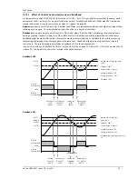
11.3
Integral Action and Manual Reset
In a full three-term controller (that is, a PID controller),
the integral term automatically removes steady state
errors from the setpoint. If the controller is set as a P
or PD controller, the integral term will be set to ‘OFF’.
Under these conditions the measured value may not
settle precisely at setpoint.
The Manual Reset parameter (
MR
) represents the value
of the power output that will be delivered when the
error is zero. This value must be set manually in order
to remove the steady state error.
11.4
Relative Cool Gain
The proportional band parameter ‘PB’ adjusts the
proportional band for the heating output. Relative cool
gain adjusts the cooling proportional band relative to
the heating proportional band. If the rate of heating
and rate of cooling are widely different it may be
necessary to manually adjust Relative Cool Gain to
achieve the optimum settings for the cooling
proportional band.
(This parameter is set automatically when Auto-tune is
used unless the parameter AT.R2G is set to ‘No’). A
nominal setting of around 4 is often used.
11.5
Control Action
When set to reverse (
R E V
) the output increases when
the PV is below setpoint. This is the best setting for
heating control.
For cooling control only set to direct (
DI R
).
11.6
On/Off Control
On/Off control simply turns heating power on when the
temperature is below setpoint and off when it is above
setpoint. If cooling is used, cooling power is turned on
when the temperature is above setpoint and off when it
is below. The outputs of such a controller will normally
be connected to relays – hysteresis may be set in the
same way as described in the Alarms section to prevent
relay chatter or to provide a delay in the control output
action.
11.7
Valve Position Control
In the 3200 series programmer/controllers two relay or
logic outputs may be configured to drive a valve in the
open direction (
UP
) or the close direction (
dwn
) via a
reversing motor drive. It operates in bounded mode
and does not require a feedback from a potentiometer
to define the valve position. The control is performed
by delivering an Up pulse, a Down pulse or no pulse at
all in response to the control demand signal via the
relay or logic outputs.
11.8
Loop Break
The loop is considered to be broken if the PV does not
respond to a change in the output. Since the time of
response will vary from process to process the
Loop
Break Time
parameter allows a time to be set before a
Loop Break Alarm
is initiated. In these circumstances
the output power will drive to high or low limit. For a
PID controller, if the PV has not moved by 0.5 x Pb in
the loop break time the loop is considered to be in
break. The loop break time is set by the Auto-tune, a
typical value is 12 x Td. For an On/Off controller Loop
Break Time is not shown and loop break alarm is
inhibited.
11.9
Cooling Algorithm
The method of cooling may vary from application to
application.
For example, an extruder barrel may be cooled by
forced air (from a fan), or by circulating water or oil
around a jacket. The cooling effect will be different
depending on the method. The cooling algorithm may
be set to linear where the controller output changes
linearly with the PID demand signal, or it may be set to
water, oil or fan where the output changes non-linearly
against the PID demand. The algorithm provides
optimum performance for these methods of cooling.


