100 MM GRAPHICS RECORDER: USER GUIDE
HA027271
Issue 12 Mar 04
User Guide
Page 86
4.6.4 INPUT ADJUST (Cont.)
ADJUST PROCEDURE
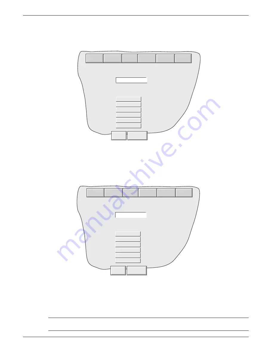
Operation of the Adjust Channels key calls the low-end adjust page, as shown in figure 4.6.4b.
Figure 4.6.4c Typical high-end input adjust page
High Point
Default value displayed, but a different value can be entered here, if required.
Apply the High point value to the relevant input channels, and wait some minutes for the recorder readings to become
stable. When the readings are stable, press the Apply key, to return to the status page.
Note: Adjusting a channel invalidates the accuracy values given in the specification in Annex A for that
channel.
Figure 4.6.4b Typical low-end input adjust page
Low Point
Usually 0, but a different value can be entered here, if required.
Apply the Low point value to the relevant input channels, and wait some minutes for the recorder readings to become
stable. When the readings are stable, press the Apply key, to call the High-end page depicted in figure 4.6.4c, below.
Specify the sensor low point and connect the
c o r r e s p o n d i n g i n p u t .
2) Channel 2
3) Channel 3
4) Channel 4
-0.0002
5) Channel 5
6) Channel 6
-0.0002
-0.0001
-0.0026
0.0000
0.0000
Unadjusted
1) Channel 1
Low Point
0
When the values below have settled select
Apply.
Unadjusted
Unadjusted
Unadjusted
Unadjusted
Unadjusted
Apply
Discard
Archive
System
Save/R.. Config
Security Network
Specify the sensor low point and connect the
c o r r e s p o n d i n g i n p u t .
2) Channel 2
3) Channel 3
4) Channel 4
4.9994
5) Channel 5
6) Channel 6
5.0010
4.9972
4.9993
5.008
5.011
Unadjusted
1) Channel 1
High Point
5
When the values below have settled select
Apply.
Unadjusted
Unadjusted
Unadjusted
Unadjusted
Unadjusted
Apply
Discard
Archive
System
Save/R.. Config
Security Network


