7100A User Manual
2-1
Installation
Chapter 2
INSTALLATION
Contents
Page
2.1. Safety during installation . . . . . . . . . . . . . . . . . . . . . . . . . . . . . . . . . . . . . . .2-2
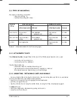
2.2. Types of mounting . . . . . . . . . . . . . . . . . . . . . . . . . . . . . . . . . . . . . . . . . . . .2-3
2.2.1. Attachment plate . . . . . . . . . . . . . . . . . . . . . . . . . . . . . . . . . . . . . . .2-3
2.2.2. Mounting / Detaching on DIN rails . . . . . . . . . . . . . . . . . . . . . . . . .2-3
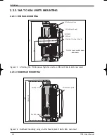
2.2.3. 16 A to 63 A units mounting . . . . . . . . . . . . . . . . . . . . . . . . . . . . . . .2-4
2.2.3.1. DIN rails mounting . . . . . . . . . . . . . . . . . . . . . . . . . . . . . . . . .2-4
2.2.3.2. Bulkhead mounting . . . . . . . . . . . . . . . . . . . . . . . . . . . . . . . .2-4
2.2.4. 80 A to 100 A units mounting . . . . . . . . . . . . . . . . . . . . . . . . . . . . . .2-5
2.2.4.1. DIN rails mounting . . . . . . . . . . . . . . . . . . . . . . . . . . . . . . . . .2-5
2.2.4.2. Bulkhead mounting . . . . . . . . . . . . . . . . . . . . . . . . . . . . . . . .2-5
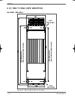
2.2.5. 125 A to 250 A units mounting . . . . . . . . . . . . . . . . . . . . . . . . . . . . .2-6
2.3. Wiring . . . . . . . . . . . . . . . . . . . . . . . . . . . . . . . . . . . . . . . . . . . . . . . . . . . .2-7
2.3.1. Power connections . . . . . . . . . . . . . . . . . . . . . . . . . . . . . . . . . . . . . .2-7
2.3.1.1. 7100 A units from 16 A to 100 A wiring diagram . . . . . . . .2-8
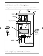
2.3.1.2. 7100 A units from 125 A to 250 A wiring diagram . . . . . . .2-9
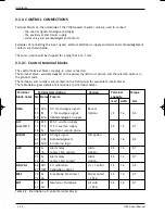
2.3.2. Control connections . . . . . . . . . . . . . . . . . . . . . . . . . . . . . . . . . . . . .2-10
2.3.2.1. Control terminal block . . . . . . . . . . . . . . . . . . . . . . . . . . . . .2-10
2.3.2.2. Control signal . . . . . . . . . . . . . . . . . . . . . . . . . . . . . . . . . . . . .2-11
2.3.2.3. Power supply for electronics . . . . . . . . . . . . . . . . . . . . . . . . .2-12
2.3.2.4. Alarm relay contact . . . . . . . . . . . . . . . . . . . . . . . . . . . . . . .2-11
2.3.2.5. Acknowledgement signal . . . . . . . . . . . . . . . . . . . . . . . . . . . .2-12
2.3.2.6. Connecting the reference neutrral voltage . . . . . . . . . . . .2-12
2.3.2.7. MSFU option, fuse blown contact . . . . . . . . . . . . . . . . . . . . .2-12
71A2_Installation_ENG_Iss3.qxp 1/09/06 16:14 Page 2-1


