7100A User Manual
2-11
Installation
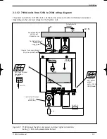
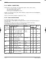
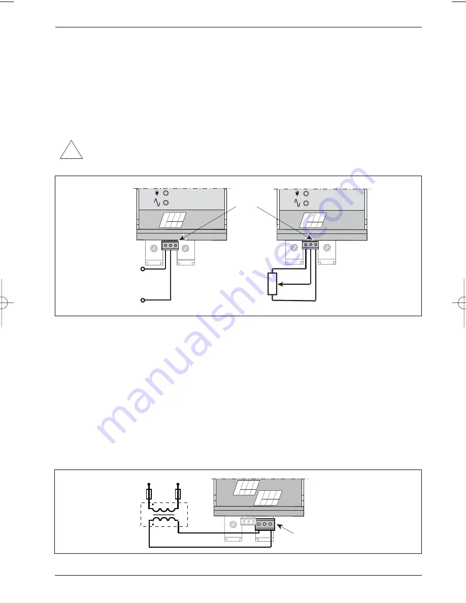
Figure 2-8 Control signal connection (self-powered unit without alarms)
a) external signal, e.g. from Eurotherm series 2000 controller
b) manual command from external potentiometer.
2.3.2.3. Power supply for electronics and fan (option) - A/F Terminal
The power supply for the electronics (auxiliary supply) may be either
• internal (self-powered, code SELF) or
• external, 115 V or 230 V depending on the product code
Only one terminal (16 for 230 V or 17 for 115 V) is available depending on the product code.
Terminal 18 (marked N) must be connected to the neutral of the external supply or to the second
phase (if the supply is taken between 2 phases).
The external supply must be
in phase with (or the opposite phase)
the line connection.
Note : This terminal block is also used for the fan power supply for 250 A units
ANA
31 0V
A
32 RI 33 5V
A
Control
signal
connector
10 k
potentiometer
For input code 0V5 only
0 V
0%
100%
In5 V (analogue signals)
0 V
+ Analogue control signal
a)
b)
ANA
31 0V
A
32 RI 33 5V
A
ON
HEAT
ON
HEAT
2.3.2.2. Control signal - ANA Terminal
The analogue control signal terminal block is labelled ANA.
The input available corresponds to the input type selected in the product code (voltage or current and
level of values). The signal must be connected between terminals 32 and 31.
A typical external signal connection is shown on figure 2-8a.
Figure 2-8b shows how to use the internal 5 V voltage (terminal 33 labelled 5VA) for manual control
with an external 10 k
Ω
potentiometer.
Important!
The control signal input is polarised.
The ‘+’ of the control signal must be connected to terminal 32 (labelled RI).
!
ANA
31 0V
A
32 RI 33 5V
A
Auxiliary supply
connector
(except self-powered)
Non-standard supply or > 500 V
Control
terminal
references
A
/F
16
2
30
17 18 N
1 A
fuses
230 V
Figure 2-9 Typical 230 V auxiliary power supply connection
71A2_Installation_ENG_Iss3.qxp 1/09/06 16:14 Page 2-11


