background image

-4- 

5.4 Configuring on Unix based Platforms ..........................................42 

Appendix A  TCP/IP Configuration for Windows 95/98..........................43 

A.1 Install TCP/IP Protocol into Your PC ..........................................43 
A.2 Set TCP/IP Protocol for Working with NAT Router ...................44 

Summary of Contents for GL2411-AR

Page 1: ...User s Manual ...

Page 2: ...ge or transmitted in any form or by any means mechanical magnetic electronic optical photocopying manual or otherwise without the prior written permission Trademarks All product company brand names are trademarks or registered trademarks of their respective companies They are used for identification purpose only Specifications are subject to be changed without prior notice ...

Page 3: ...his manual may cause harmful interference to radio communications Operation of this equipment in a residential area is likely to cause interference in which case the user at his own expense will be required to take whatever measures are necessary to correct the interference CE Declaration of Conformity This equipment complies with the requirements relating to electromagnetic compatibility EN 55022...

Page 4: ...ter 13 3 2 Install the Software into Your Computers 14 Chapter 4 Configuring Wireless Broadband Router 17 4 1 Start up and Log in 17 4 2 Status 19 4 3 Toolbox 20 4 4 Primary Setup 21 4 5 DHCP Server 24 4 6 Virtual Server 26 4 7 Special AP 28 4 8 Access Control 29 4 9 Misc Items 31 4 10 Wireless Setting 33 4 11 MAC Address Control 35 Chapter 5 Print Server 38 5 1 Configuring on Windows 95 98 Platfo...

Page 5: ... 4 5 4 Configuring on Unix based Platforms 42 Appendix A TCP IP Configuration for Windows 95 98 43 A 1 Install TCP IP Protocol into Your PC 43 A 2 Set TCP IP Protocol for Working with NAT Router 44 ...

Page 6: ...nctions of this product 1 1 Functions and Features l High speed for wireless LAN connection 11Mbps data rate by incorporating Direct Sequence Spread Spectrum DSSS l Roaming Provides seamless roaming within the IEEE 802 11b WLAN infrastructure l IEEE 802 11b compatible Allowing inter operation among multiple vendors l Auto fallback 11M 5M 2M 1M data rate with auto fallback l Broadband modem and NAT...

Page 7: ...ign different access right for different users l Virtual Server supported Enables you to expose WWW FTP and other services on your LAN to be accessible to Internet users l User DefinableApplication Sensing Tunnel User can define the attributes to support the special applications requiring multiple connections like Internet gaming video conferencing Internet telephony and so on then this product ca...

Page 8: ... 7 Provides firmware upgrade via Web Browser or Windows Application 1 2 Packing List l Wireless broadband router unit l Installation CD ROM l Power adapter l CAT 5 UTP Fast Ethernet cable ...

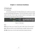
Page 9: ...our DSL or cable modem to the router The LAN ports are used to connect to your computers or other network devices LEDs monitor the status of each port Figure 2 1 Front Panel Port WAN the port where you will connect your cable or DSL modem or Ethernet router Port 1 4 the ports where you will connect networked computers and other devices UPLINK the port where you will connect another hub to expand y...

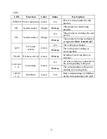
Page 10: ...s being configured or upgraded Don t turn it off On The LAN port is linked LAN LAN port activity Green Blinking The LAN port is sending or receiving data WLAN Wireless activity Green Blinking Sending or receiving data via wireless On An active station is connected to the corresponding LAN port Link Act 1 4 Link status Green Blinking The corresponding LAN port is sending or receiving data 10 100 1 ...

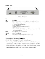
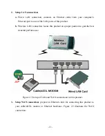
Page 11: ...h once per second 12VDC Power inlet DC 12V 1 2A minimum PRINTER Printer Port Optional COM Serial port connect analog modem or console cable 2 2 Procedure for Hardware Installation 1 Decide where to place your Wireless Broadband Router You can place your Wireless Broadband Router on a desk or other flat surface or you can mount it on a wall For optimal performance place your Wireless Broadband Rout...

Page 12: ...his product b Wireless LAN connection locate this product at a proper position to gain the best transmit performance Figure 2 3 Setup of LAN and WAN connections for this product 3 Setup WAN connection prepare an Ethernet cable for connecting this product to your cable xDSL modem or Ethernet backbone Figure 2 3 illustrates the WAN connection ...

Page 13: ... turning the power switch on this product will automatically enter the self test phase When it is in the self test phase the indicators M1 and M2 will be lighted ON for about 10 seconds and then M1 and M2 will be flashed 3 times to indicate that the self test operation has finished Finally the M1 will be continuously flashed once per second to indicate that this product is in normal operation ...

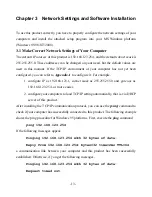
Page 14: ...le 1 configure IP as 192 168 123 1 subnet mask as 255 255 255 0 and gateway as 192 168 123 254 or more easier 2 configure your computers to load TCP IP setting automatically that is via DHCP server of this product After installing the TCP IP communication protocol you can use the ping command to check if your computer has successfully connected to this product The following example shows the ping ...

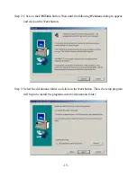
Page 15: ...he TCP IP environment of your computers properly configured Tip If the IP address of this product is 192 168 123 254 the IP address of your computer must be 192 168 123 X and default gateway must be 192 168 123 254 3 2 Install the Software into Your Computers Skip this section if you do not want to use the print server function of this product Step 1 Insert the installation CD ROM into the CD ROM ...

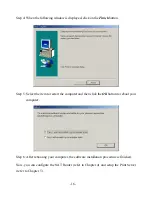
Page 16: ...tton Wait until the following Welcome dialog to appear and click on the Next button Step 3 Select the destination folder and click on the Next button Then the setup program will begin to install the programs into the destination folder ...

Page 17: ... 5 Select the item to restart the computer and then click the OK button to reboot your computer Step 6 After rebooting your computer the software installation procedure is finished Now you can configure the NAT Router refer to Chapter 4 and setup the Print Server refer to Chapter 5 ...

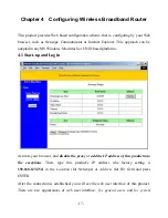
Page 18: ...NIX based platforms 4 1 Start up and Log in Activate your browser and disable the proxy or add the IP address of this product into the exceptions Then type this product s IP address the factory setting is 192 168 123 254 in the Location for Netscape or Address for IE field and press ENTER After the connection is established you will see the web user interface of this product There are two appearan...

Page 19: ...sword the factory setting is admin in the System Password field and click on the Log in button If the password is correct the web appearance will be changed into administrator configure mode As listed in its main menu there are several options for system administration ...

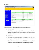
Page 20: ... a Renew or Release button on theSidenote column You can click this button to renew or release IP manually B Modem Status C Printer Status The possible kinds of printer status include Ready Not ready Printing and Device error When a job is printing there may appear a Kill Job button on the Sidenote column You can click this button to kill current printing job manually ...

Page 21: ...is device Backup Setting You can backup your settings by clicking this button and save it as a bin file Once you want to restore these settings please click Firmware Upgrade button and use the bin file you saved Reset to Default Reset the settings of this device to the default values Firmware Upgrade Prompt the administrator for a file and upgrade it to this device Note we strongly recommend you t...

Page 22: ...use the LAN IP address of your product as their Default Gateway You can change it if necessary 2 WAN Type WAN connection type of your ISP You can click Change button to choose a correct one from the following four options A Static IP Address ISP assigns you a static IP address B Dynamic IP Address Obtain an IP address from ISP automatically C PPP over Ethernet Some ISPs require the use of PPPoE to...

Page 23: ...e optional Input the service name if your ISP requires it Otherwise leave it blank 3 Maximum Idle Time the amount of time of inactivity before disconnecting your PPPoE session Set it to zero or enable Auto reconnect to disable this feature 4 4 4 Dial up Network 1 Dial up Telephone Account and Password assigned by your ISP For security this field appears blank If you don t want to change the passwo...

Page 24: ... 23 quality between the ISP and your MODEM or ISDN TA ...

Page 25: ...able this product s DHCP server and configure your computers as automatic IP allocation mode then when your computer is powered on it will automatically load the proper TCP IP settings from this product The settings of DHCP server include the following items 1 DHCPServer Choose Disable or Enable 2 Range of IP Address Pool Whenever there is a request the DHCP server will automatically allocate an u...

Page 26: ... Clients List List the current mapping of the IP and MAC address for each DHCP client Fixed Mapping In general DHCP server assigns an IP address chosen from the IP addresses pool randomly Fixed Mapping allows you to assign a specific IP address to the specified MAC address ...

Page 27: ...some of them accessible by enabling the Virtual Server Mapping A virtual server is defined as a Service Port and all requests to this port will be redirected to the computer specified by the Server IP For example if you have an FTP server port 21 at 192 168 123 1 a Web server port 80 at 192 168 123 2 and a VPN server at 192 168 123 6 then you need to specify the following virtual server mapping ta...

Page 28: ... 27 Service Port Server IP Enable 21 192 168 123 1 V 80 192 168 123 2 V 1723 192 168 123 6 V ...

Page 29: ...hanism of Special Applications fails to make an application work try setting your computer as the DMZ host instead 1 Trigger the outbound port number issued by the application 2 Incoming Ports when the trigger packet is detected inbound packets sent to the specified port numbers are allowed to pass through the firewall This product provides some predefined settings Select your application and clic...

Page 30: ...hers are all members of Default Group Second you have to assign the access right for each group Access right can allow or block for access specified TCP and UDP ports For example Group Members Access Right Comments Default Allow No access right allow nothing Group 1 50 99 Allow 25 53 Can browse 80 receive 110 and send 25 email only Group 2 100 199 Block 21 119 Cannot read net news 119 and FTP 21 o...

Page 31: ...address only If a user is able to change his IP address the user will be out of control The MAC level access control allows you to control the mapping of MAC addresses and IP addresses You can also control which MAC address is allowed to connect to this device ...

Page 32: ...te Administrator Host In general only Intranet users can browse the built in web pages to perform administration task If this feature is enabled only the specified IP address can perform remote administration If the specified IP address is 0 0 0 0 any remote host can connect to the product to perform administration tasks When this feature is enabled the web port will be shifted to 88 3 Administrat...

Page 33: ... When this feature is enabled hosts on the WAN cannot ping this product 5 Non standard FTP port You have to configure this item if you want to access an FTP server whose port number is not 21 This setting will be lost after rebooting ...

Page 34: ...t have the same Network ID The factory setting is default 2 Channel The radio channel number The permissible channels depend on the Regulatory Domain The factory setting is as follows USA Canada Europe Australia ETSI Japan All Channel 6 Spain France Channel 10 Japan Channel 14 3 WEP Security Select the data privacy algorithm you want Enabling the security can protect your data while it is transfer...

Page 35: ...y 1 2 3 4 When you enable the 64 bit or 128 bit WEP key security please select one WEP key to be used and then input 10 or 26 hex decimal 0 9 A F digits MAC Address Control Setup MAC addresses to control which wireless clients can associate to the wireless LAN ...

Page 36: ...able the MAC Address Control All of the settings in this page will take effect only when Enable is checked Connection control Check Connection control to enable the controlling of which wired and wireless clients can connect to this device If a client is denied to connect to this device it means the client can t access to the Internet either Choose allow or deny to allow or deny the clients whose ...

Page 37: ... associate to the wireless LAN Control table Control table is the table at the bottom of the MAC Address Control page Each row of this table indicates the MAC address and the expected IP address mapping of a client There are four columns in this table MAC Address MAC address indicates a specific client IP Address Expected IP address of the corresponding client Keep it empty if you don t care its I...

Page 38: ...t in the DHCP clients Combobox and then click on the Copy to button to copy the MAC address of the client you select to the ID selected in the ID Combobox Previous page and Next Page To make this setup page simple and clear we have divided the Control table into several pages You can use these buttons to navigate to different pages ...

Page 39: ...figuring on Windows 95 98 Platforms After you finished the software installation procedure described in Chapter 3 your computer has possessed the network printing facility provided by this product For convenience we call the printer connected to the printer port of this product as server printer On a Windows 95 98 platform open the Printers window in the My Computer menu Now yon can configure the ...

Page 40: ... 39 1 Find out the corresponding icon of your server printer for example the HP LaserJet 6L Click the mouse s right button on that icon and then select the Properties item 2 Click the Details item ...

Page 41: ...rinter 4 Click on the button of Port Settings Type in the IP address of this product and then click the OK button 5 Make sure that all settings mentioned above are correct and then click theOK button 5 2 Configuring on Windows NT Platforms The configuration procedure for a Windows NT platform is similar to that of Windows 95 98 except the screen of printer Properties ...

Page 42: ... Configure Port 5 3 Configuring on Windows 2000 Platforms The configuration procedure for a Windows 2000 platform is similar to that of Windows 95 98 except the screen of printer Properties Compared to the procedure in last section the selection of Details is equivalent to the selection of Ports and Port Settings is equivalent to Configure Port ...

Page 43: ... 42 5 4 Configuring on Unix based Platforms Please follow the traditional configuration procedure on Unix platforms to setup the print server of this product The printer name is lp ...

Page 44: ...not please refer to your network card manual Moreover the Section A 2 tells you how to set TCP IP values for working with this NAT Router correctly A 1 Install TCP IP Protocol into Your PC 1 Click Start button and choose Settings then click Control Panel 2 Double click Network icon and select Configuration tab in the Network window 3 Click Add button to add network component into your PC 4 Double ...

Page 45: ... button to return to Network window 6 The TCP IP protocol shall be listed in the Network window Click OK to complete the install procedure and restart your PC to enable the TCP IP protocol A 2 Set TCP IP Protocol for Working with NAT Router 1 Click Start button and choose Settings then click Control Panel ...

Page 46: ...the TCP IP line that has been associated to your network card in the Configuration tab of the Network window 3 Click Properties button to set the TCP IP protocol for this NAT Router 4 Now you have two setting methods A Get IP via DHCP server ...

Page 47: ... 46 a Select Obtain an IP address automatically in the IP Address tab ...

Page 48: ... 47 b Don t input any value in the Gateway tab ...

Page 49: ... 48 c Choose Disable DNS in the DNS Configuration tab ...

Page 50: ...y a Select Specify an IP address in the IP Address tab The default IP address of this product is 192 168 123 254 So please use 192 168 123 xxx xxx is between 1 and 253 for IP Address field and 255 255 255 0 for Subnet Mask field ...

Page 51: ... 50 b In the Gateway tab add the IP address of this product default IP is 192 168 123 254 in the New gateway field and click Add button ...

Page 52: ... 51 c In the DNS Configuration tab add the DNS values which are provided by the ISP into DNS Server Search Order field and click Add button ...

Reviews: