Electrical installation instructions | Elektrische installatie instructies
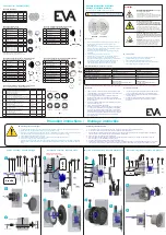
EN Remove the side-covers from the power supply
with a screwdriver.
NL Verwijder de blauwe zijkapjes van de power supply
met een schroevendraaier.
EN Open the PSU and mount the included cable glands
in the pre-drilled holes. Close the not used holes with
a rubber ring and cable gland plug.
NL Open de voedingskast en monteer de
bijgeleverde wartels in de voorgeboorde gaten. Dicht
vervolgens de niet gebruikte gaten af met een rubberen
ring en wartel stop.
EN Connect the black wire from the light unit, to the V- on
the driver.
NL Sluit de zwarte draad van het armatuur aan op V-
van de driver.
N
L
EN Connect the live wire (AC) with the power supply.
Connect phase (black) to ACL/DC+. Connect Null (blue)
to ACN/DC-. Place the blue side caps back on the
original position and screw them back on. Make sure
the cable is not pinched.
NL Verbind de voedingskabel (AC) met de voeding.
Verbind fase (zwart) naar ACL/DC+. Verbind Nul (blauw)
naar ACN/DC-. Plaats de blauwe zijkapjes weer terug op
positie en schroef deze weer vast. Let op dat de kabel
niet bekneld komt.
Light Colour:
White
Connect wire to V+:
Sluit draad aan op V+:
White
Light Colour:
Blue
Connect wire to V+:
Sluit draad aan op V+:
Blue
Light Colour:
Red
Connect wire to V+:
Sluit draad aan op V+:
Red
Light Colour:
Green
Connect wire to V+:
Sluit draad aan op V+:
Green
Light Colour:
Mediterranean Blue
Connect wire to V+:
Sluit draad aan op V+:
Green
& Blue
Light Colour:
Sky Blue
Connect wire to V+:
Sluit draad aan op V+:
White
& Blue
EN Choose the desired light colour (see images of
colour options below). Connect the corresponding
wire(s) to V+. When using 2 coloured wires, tighten
both wires together before inserting them into the
slot.
NL Kies de gewenste lichtkleur (zie afbeelding met
mogelijkheden hieronder). Verbind de corresponderen-
de kabels in V+. Indien twee gekleurde draden worden
gebruikt (bvb sky blue = blauw + wit), draai de twee
draden goed samen aan alvorens deze in de opening te
steken.
EN After connecting the V- (black wire) and the V+
(coloured wire), the remaining unused wires has to be
cut at the base of the cable or tied up to each other
with a ty-rap. After that you can close the PSU.
NL Na het aansluiten van V- (zwarte draad) en V+
(gekleurde draad), worden de overgebleven
ongebruikte draden afgeknipt bij de basis van de kabel
of met een ty-rap aan elkaar opgebonden. Sluit
vervolgens de voedingskast.
NOTE: only use above colours. Any other combination may harm the luminaire!
LET OP: gebruik alleen bovenstaande opties, andere opties kunnen het armatuur beschadigen!
EN Connect AC with the input cable of the driver by using a
Wago connector.
NL Verbind de voedingskabel (AC) met de input kabel van de
driver door middel van een Wago connector.
Power input
(AC
)
Power output
(DC)
V-
EN Connect the black wire of the light unit to V- (3).
NL Sluit de zwarte draad van het armatuur aan op V- (3).
IMPORTANT! Switch off all relevant live wiring before starting the installation.
EN Choose the desired light colour (see images of colour
options below). Connect the corresponding wire(s) to
V+ (N). When using 2 coloured wires, tighten both wires
together before inserting them into the slot.
NL Kies de gewenste lichtkleur (zie afbeelding met
mogelijkheden hieronder). Sluit de betreffende draad
(van de gewenste kleur) aan op V+ (N). Indien 2 gekleurde
draden worden gebruikt (bvb sky blue = blauw + wit),
draai de twee draden goed samen aan alvorens deze in de
opening te steken.
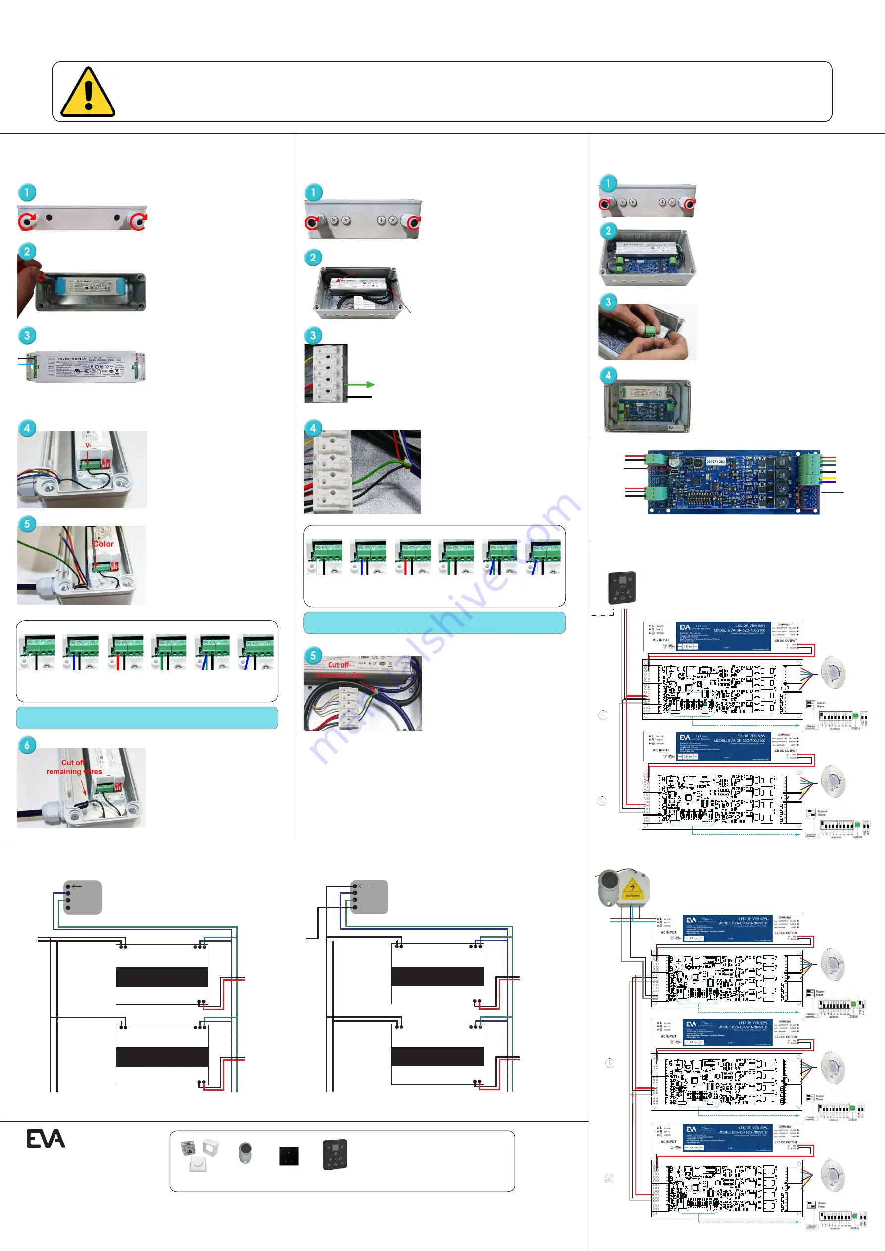
EN Connect the cable from the lamp to the green PDTA
connector on the blue printed circuit board (PCB) in the
correct order, as shown below. After successful connection,
place the connector back on the blue PCB.
NL Verbind de kabel van de lamp met de groene connector
op de blauwe printplaat in de correcte volgorde, zie hieronder.
Plaats dan de aangesloten connector terug op de printplaat.
CH1 = Red
CH4 = White
NTC = Yellow
CH2 = Green
CH5 = Black
NTC = Purple
CH3 = Blue
EN After connecting power input and output, close the power
supply unit.
NL Na het verbinden van de kabels, sluit de PSU door middel
van het plaatsen van de deksel. Draai deze handvast.
EV
A Op
tic
Dimming pack
+ - L
EVA Optic driver
A6/A12
LED DC output
Dimming
AC input
ACL (BLK)
ACN
(WHT)
GN
D (GRN
)
1-10V (PUR)
10V (YL
W)
V- (BLK
)
V+ (RED)
EVA Optic driver
A6/A12
LED DC output
Dimming
AC input
ACL (BLK)
ACN
(WHT)
GN
D (GRN
)
1-10V (PUR)
10V (YL
W)
V- (BLK
)
V+ (RED)
Maximum 28x A6/A12 lights per dimming pack
Connect to
next driver
Sluit aan op
volgende driver
!
EV
A Op
tic
Dimming pack
+ - L
EVA Optic driver
A6/A12
LED DC output
Dimming
AC input
ACL (BLK)
ACN
(WHT)
GN
D (GRN
)
1-10V (PUR)
10V (YL
W)
V- (BLK
)
V+ (RED)
EVA Optic driver
A6/A12
LED DC output
Dimming
AC input
ACL (BLK)
ACN
(WHT)
GN
D (GRN
)
1-10V (PUR)
10V (YL
W)
V- (BLK
)
V+ (RED)
Maximum 28x A6/A12 lights per dimming pack
Connect to
110-240 Vac
Sluit aan op
110-240 Vac
!
NTC
ADDRESS
256
128
64
32
16
8
4
2
1
M
S
Status
Data-bus
terminator
LED Driver
EVA
D
E
Slave
Master
NTC
ADDRESS
256
128
64
32
16
8
4
2
1
M
S
Status
Data-bus
terminator
LED Driver
EVA
D
E
Slave
Master
Do not
connect
DMX shield
to ground
of power
supply!
Use EVA
Optic
DMX cable
(green)
EVA-AA-96
!
Gebruik
EVA Optic
DMX kabel
(groen)
EVA-AA-96
Power 24VDC
or PoE!
(Power over
Ethernet)
A6/A12 Mono - Dimming pack
Dimming 10% - 100%
A6/A12 Mono - Dimming pack
Dimming 10% - 100% & ON/OFF
A6/A12 RGBW - DMX control
ArchiTech EVO DMX Control unit
A6/A12 RGBW - Remote control
EVA-AA-73
EVA-AA-78
EVA-AA-75
EVA-AA-74
EVA-AA-73
Dimming pack (only for mono colour luminaires)
EVA-AA-74
Remote control Multicolour
EVA-AA-75
DMX Control unit ArchiTech
EVA-AA-78
DMX Control unit ArchiTech EVO
EVA-AA-96
EVA DMX cable
EVA-AA-98-7 EVA Aquacable RGBW 7-wired
For manuals and DMX software please visit the support page on our website: www.evaoptic.com
EVA Optic B.V.
De Velde 1
8064 PH
Zwartsluis
The Netherlands
info@evaoptic.com
www.evaoptic.com
Sluit DMX
mantel niet
aan op de
aarde van
de voeding!
Colour Options
Kleuropties:
240V
NTC
ADDRESS
256
128
64
32
16
8
4
2
1
M
S
Status
Data-bus
terminator
LED Driver
EVA
D
E
Slave
Master
NTC
ADDRESS
256
128
64
32
16
8
4
2
1
M
S
Status
Data-bus
terminator
LED Driver
EVA
D
E
Slave
Master
NTC
ADDRESS
256
128
64
32
16
8
4
2
1
M
S
Status
Data-bus
terminator
LED Driver
EVA
D
E
Slave
Master
First driver
Eerste driver
Next Driver(s)
Volgende driver(s)
Last
driver
Laatste driver
L
N
First & next drivers
Eerste & volgende drivers
Last
driver
Laatste driver
Connect to
110-240 Vac
Sluit aan op
110-240 Vac
Connect to
next driver
Sluit aan op
volgende driver
Connect to
next driver
Sluit aan op
volgende driver
Connect to
next driver
Sluit aan op
volgende driver
Output
V+
V-
CH1 Red
CH2 Green
CH3 Blue
CH4 White
GND Black
Input 24DC
EN: Blue PCB. Left side is input, right side is output. Colours of the cables can differ, make sure using the correct cable.
For CH8 different programming is needed, please inform EVA Optic if you want to use this option.
DMX +
DMX -
DMX GND
NTC Yellow
NTC Purple
Input DMX
0-10V Output
CH5
0-10V |GND
CH6
0-10V |GND
CH7
0-10V |GND
0-10V Output
CH8
0-10V
EVA Optic B.V. | www.evaoptic.com | info@evaoptic.com | +31 (0)38 - 33 75 067 | Version 16.1
IMPORTANT! Switch off all relevant live wiring before starting the installation.
1. Always use one power supply per luminaire.
2. Mount the power supply box in a dry, cool area.
3. Allow at least 5 cm of space around the power supply box for efficient thermal management.
4. Mount the power supply box always with cable glands downwards.
5. Electrical connection according to the supplied wiring diagram.
LET OP! Schakel alle relevante spanningsvoerende bekabeling uit alvorens met de installatie te starten.
1. Gebruik altijd 1 voeding per armatuur.
2. Monteer de voedingskast in een droge, koele ruimte.
3. Zorg voor minimaal 5 cm ruimte rondom de voedingskast voor een efficiënte warmtehuishouding.
4. Monteer de voedingskast altijd met de wartels naar beneden.
5. Elektrische aanlsuiting volgens het bijgeleverde schema.
A6 Mono
IMPORTANT! Switch off all relevant live wiring before starting the installation.
A12 Mono
IMPORTANT! Switch off all relevant live wiring before starting the installation.
A6/A12 RGBW
EN Important! For addressing the lights use binary DMX count or use
a DIP switch calculator.
NL Belangrijk! Voor het adresseren van de lampen gebruik binaire DMX
telling of gebruik een DIP switch calculator.
EN Use this diagram for connecting drivers to:
- Pulse switch
- Remote control
NL Gebruik dit schema voor het verbinden van drivers met:
- Pulse switch
- Afstandsbediening
Technical additions and/or changes and printing errors do not constitute grounds for compensation claims.
Technische aanvulling en/of wijzigingen en drukfouten geven geen aanspraak op een schadevergoeding.
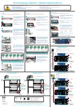
EN Open the PSU and mount the included cable glands
in the pre-drilled holes. Close the not used holes with a
rubber ring and cable gland plug.
NL Open de voedingskast en monteer de
bijgeleverde wartels in de voorgeboorde gaten. Dicht
vervolgens de niet gebruikte gaten af met een rubberen
ring en wartel stop.
EN Open the PSU and mount the included cable glands in the
pre-drilled holes. Close the not used holes with a rubber ring
and cable gland plug.
NL Open de voedingskast en monteer de bijgeleverde wartels
in de voorgeboorde gaten. Dicht vervolgens de niet gebruikte
gaten af met een rubberen ring en wartel stop.
Color
EN Connect AC with the input cable of the driver by using a
Wago connector.
NL Verbind de voedingskabel (AC) met de input kabel van de
driver door middel van een Wago connector.
EN After connecting the V- (black wire) and the V+
(coloured wire), the remaining unused wires has to be
cut at the base of the cable or tied up to each other with
a ty-rap. After that you can close the PSU.
NL Na het aansluiten van V- (zwarte draad) en V+
(gekleurde draad), worden de overgebleven
ongebruikte draden afgeknipt bij de basis van de kabel
of met een ty-rap aan elkaar opgebonden. Sluit
vervolgens de voedingskast.
Light Colour:
White
Connect wire to V+:
Sluit draad aan op V+:
White
Light Colour:
Blue
Connect wire to V+:
Sluit draad aan op V+:
Blue
Light Colour:
Red
Connect wire to V+:
Sluit draad aan op V+:
Red
Light Colour:
Green
Connect wire to V+:
Sluit draad aan op V+:
Green
Light Colour:
Mediterranean Blue
Connect wire to V+:
Sluit draad aan op V+:
Green
& Blue
Light Colour:
Sky Blue
Connect wire to V+:
Sluit draad aan op V+:
White
& Blue
NOTE: only use above colours. Any other combination may harm the luminaire!
LET OP: gebruik alleen bovenstaande opties, andere opties kunnen het armatuur beschadigen!
Colour Options
Kleuropties:
!
Do not
connect
DMX shield
to ground
of power
supply!
Use EVA
Optic
DMX cable
(green)
EVA-AA-96
!
Gebruik
EVA Optic
DMX kabel
(groen)
EVA-AA-96
Sluit DMX
mantel niet
aan op de
aarde van
de voeding!
!
Connect to A6/A12
Sluit aan op A6/A12
Standard 10m (7-wired) extend
up to max. 100m with 2,5mm²
Standaard 10m (7-aderig)
te verlengen tot max. 100m
met 2,5mm²
Max. 30m (7-wired) extend up
to max. 50m with 2,5mm²
Max. 30m (7-aderig) te verlengen
tot max. 50m met 2,5mm²
Optional!
Connect to A6/A12
Sluit aan op A6/A12
Standard 10m (7-wired) extend
up to max. 100m with 2,5mm²
Standaard 10m (7-aderig)
te verlengen tot max. 100m
met 2,5mm²
Max. 30m (7-wired) extend up
to max. 50m with 2,5mm²
Max. 30m (7-aderig) te verlengen
tot max. 50m met 2,5mm²


