background image

EVCO | 21.10.2020 | AZ

| 29

144EJBSI104

EVLJBOX HP Sequencer - 

Application manual

Main regulation

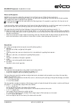
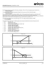
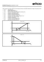
Main regulation is a regulation in the incremental neutral zone based on the differential from the temperature setpoint of 
the regulation temperature. The procedure will be different according to the operating mode set by parameter 

MOdE

.

Every time the operating mode changes, regulation is blocked for 30 seconds to prevent communication problems with the 
slaves.

When heat regulation is requested, a slave is activated and incremented up to 100%, according to the regulation timing set. 
It will then move on to the next slave, incrementing it by 100%, and continue in this manner until the maximum number of 

slaves configured have been incremented.  

Vice versa, when the request for heat regulation expires, one slave is decreased to 0% and then deactivated. It will then 

move on to the next slave, decreasing it to 0%, and continue in this manner until it has run down all the configured slaves.

It is possible to restrict the number of slaves to activate simultaneously by leaving the remaining slaves in stand-by through 
parameter 

PG02

.

Two dedicated setpoints will be loaded according to the operating mode:


Summer mode/cooling (

MOdE = 0


the summer setpoint set by parameter 

SEtC


will be loaded


Winter mode/heating (

MOdE = 1


the winter setpoint set by parameter 

SEtH


will be loaded

In CHILLER slaves where the machine is a chiller only (

PG01 = 0

 or 

PG01 = 2

), the operating mode is limited to summer mode 

only and any changes made to parameter 

MOdE

 will have no effect.

The application, which decides the regulation probe to use, will interrogate the slaves in a register called MODBUS to find 

out if they are reversible or non-reversible. 
As regards HPRU slaves, the kind of condenser set by parameter 

PF60


will be taken into consideration

:


if 

PF60 = 0

 (air) or 

PF60 = 2

 (water) the machine is reversible


if


PF60 = 1

 (water) the machine is not reversible

For 

CHILLER slaves, the type of machine set by parameter 

PG01 will be taken into consideration

:


if 

PG01 = 0

 (Air-Water chiller only) or 

PG01 = 2

 (Water-Water chiller only) the machine is not reversible


if 

PG01 = 1

 (Air-Water HP) or 

PG01 = 3

 (Water-Water HP) the machine is reversible

If the operating mode is set to winter (

MOdE = 1

) and the slaves are not reversible, the regulation probe will be the 

condenser output probe.   In all other cases, the evaporator output probe will be taken into consideration. 

Regulation will be blocked in the following cases:


MODBUS communication not yet enabled after the sequencer has been switched on 


Regulation probe disconnected or showing an error


Slave configuration alarm due to discrepancies between the types of slaves (HPRU and CHILLER in the same network) or 

between the types of condenser (air and water reversible/non reversible in the same network)

A request for heat regulation is made if:


In summer: the regulation temperature is above the setpoint 

SEtC

 plus the neutral zone 

Pr01/2


In winter: the regulation temperature is below the setpoint 

SEtH

 minus the neutral zone 

Pr01/2

The request will be met if:


In summer: the regulation temperature is below the setpoint 

SEtC

 minus the neutral zone


Pr01/2


In winter: the regulation temperature is above the setpoint 

SEtH

 plus the neutral zone 

Pr01/2

Summary of Contents for EVLJBOX HP Sequencer

Page 1: ...olution LCD colour graphic display 6 capacitive touch keys Electrical panel with full IP65 Display of the main variables of each heat pump Management of the main equipment functions Management of up to 5 heat pumps Automatic power modulation Maximum number of active units set by parameter Applications Heat pump ...

Page 2: ...tions before using the device Keep this document with the device for future reference Only use the device in the ways described in this document CONSIDER THE ENVIRONMENT Please read this document carefully and save it DISPOSAL The device must be disposed of according to local regulations governing the collection of electrical and electronic equipment ...

Page 3: ...rs 10 Electrical connection 12 User interface 13 Keypad 13 List of pages 14 Password 14 Main page 15 Status pages 17 Main menu 18 User menu 18 Servicer menu 19 Installer menu 19 RTC menu 20 Alarm menu 21 Alarm history menu 21 Save reset menu 21 Info menu 22 List of parameters 23 Description of parameters 23 Structure of the menus 23 Configuration parameters table 24 Regulations 28 Machine status 2...

Page 4: ...atic alarms 34 Manual alarms 34 Automatic alarms 34 Table of alarms 35 Blocking alarms for the master 35 Blocking alarms for the slaves 35 Slave configuration alarm 37 Slave communication alarm 37 Evaporator high low temperature alarm 38 Condenser high low temperature alarm 39 Technical specifications 40 ...

Page 5: ...e number of operating units and their power level are adjusted according to the cooling heating requirements of the equipment but it is also possible to set parameters for the number of units active at the same time The fully IP65 compliant panel houses a user interface with a LCD graphic display with a resolution of 320x240 pixels and 16 colours from which it is possible to manage all the main fu...

Page 6: ...er return water temperature probe PTC NTC PT1000 Analogue outputs Evaporator mixing valve 0 10 V PWM Condenser mixing valve 0 10 V PWM Digital outputs Heating cooling switching valve 1 5 A Heating cooling switching valve 2 5 A User interface 320x240 px with LCD colour graphic display Dimensions 150x245 mm Installation Wall mounted Connections Fixed screw terminal blocks Type A female USB connector...

Page 7: ...EVCO 21 10 2020 AZ 7 004_EVLJBOX_Sequencer_Dimensioni_001_0 1_AZ 144EJBSI104 EVLJBOX HP Sequencer Application manual Measurements 150 mm 88 6 mm 245 mm ...

Page 8: ...ecure the back cover 7 to the wall using the 4 screws 1 and the holes already made 6 2 Make sure the seal 8 is correctly inserted 3 Place the front cover 4 over the back cover 7 and push the 2 assembling tongues 10 down into the holes 2 on the right or left of the front cover 4 4 Fix the user interface 12 into place by pressing it into its housing 5 from the front 5 Fix the control module 14 to th...

Page 9: ...er Make sure that the supply voltage electrical frequency and power are within the set limits Disconnect the power supply before carrying out any type of maintenance Do not use the device as a safety device For repairs and further information contact the EVCO sales network returned goods without the data label will not be accepted Connector 2 Micro switch Connector 1 User interface Connector 1 Num...

Page 10: ...on contact NO4 K4 digital output normally open contact 5 A res at 250 VAC CO5 K5 digital output common contact NO5 K5 digital output normally open contact 5 A res at 250 VAC Connector 3 Number Description NO6 K6 digital output normally open contact 16 A res at 250 VAC CO6 K6 digital output common contact NC6 K6 digital output normally closed contact Connector 4 Number Description DIHV1 DI1 high vo...

Page 11: ...logue input for PTC NTC or Pt 1000 probes can also be configured for DI10 dry contact digital input IN5 AI5 analogue input for PTC NTC or Pt 1000 probes can also be configured for DI9 dry contact digital input IN4 AI4 analogue input for PTC NTC or Pt 1000 probes can also be configured for DI8 dry contact digital input IN3 AI3 analogue input for NTC probes 0 5 V 0 10 V 0 20 mA or 4 20 mA transd can...

Page 12: ...lve 1 Heating cooling switching valve 2 heat pump EVCO 5 heat pump EVCO 4 heat pump EVCO 3 heat pump EVCO 2 heat pump EVCO 1 Evaporator mixing valve Condenser return water temp probe Condenser supply water temp probe Fan return water temp probe Fan supply water temp probe Mains supply 230 VAC Power supply 115 230 VAC Control module User interface ...

Page 13: ... power supply Access to menus Keys Instructions Hold the ENTER key down for 2 seconds the display will show the main screen Press the UP or DOWN key to select the menus Press the ENTER key to confirm the menu Press the ENTER key to access the value Press the UP or DOWN key to set the value Press the ENTER key to confirm the value Press the ON STAND BY key a few times to return to the previous disp...

Page 14: ...S Default Miscellaneous Password RTC menu Level 0 ALARM menu Level 0 Master Slave HISTORY menu Level 0 SAVE RESET menu Level 0 Flash drive Memory INFO menu Level 0 Password Each menu level sets the accessibility to the various functions and it is assigned a password Once the correct password has been entered users can Access protected functions Unlock the level in question Unlock the various suble...

Page 15: ...d for 2 seconds MODBUS communication with the slaves will begin The system off page will be displayed on the sequencer with the following information Active alarms in the master and relative number no alarm active at least one alarm active Current date and time Software version Command to switch on the sequencer system To prevent the sequencer being accidentally switched on which could cause probl...

Page 16: ...umber of active slaves if an alarm occurs with one of the slaves the alarm icon will flash every 2 seconds minor alarm blocking alarm Condenser output temperature shown only with slave with water condenser Evaporator output temperature Power required by the system System power output Command to switch sequencer off If there is an error with a probe or if it is disconnected will appear in the field...

Page 17: ...nd regulation neutral zone Power required by the master Slave power output Number of active slaves Slave screen This screen displays the following information regarding each slave Slave status no alarm active at least one minor alarm active at least one blocking alarm active Regulation status ALARM at least one blocking alarm is active in the slave UNIT OFF slave off READY slave enabled and ready ...

Page 18: ... mixing valve screen This screen displays the following information regarding the condenser valve Temperature of regulation probe Current regulation setpoint Regulation differential Regulation request Analogue output valve value evaporator mixing valve screen condenser mixing valve screen user menu Main menu The main menu has no level and is the access point for all the other system menus It is po...

Page 19: ...sical board inputs and outputs can be viewed directly here password menu the servicer level level 2 password can be set here Installer menu The installer menu is level 3 and it is therefore necessary to enter the installer level password or that of a higher level to view change the parameters in this section All the parameters regarding the configuration of the functions can be found in the instal...

Page 20: ...N network can be viewed in this menu MODBUS menu all the parameters to configure the network on the RS 485 port can be viewed in this menu default menu the default values of all the application parameters can be reset in this menu miscellaneous menu this contains other general parameters such as enabling system start up stop by the supervisor setting the language setting the temperature measuremen...

Page 21: ... ALARMS will appear on the screen Press the ENTER key for about 2 seconds to reset the alarm if the error conditions are no longer active Press the ON STAND BY key or wait 60 seconds without pressing any key to return to the main page Alarm history menu The alarm history menu displays the alarm history showing the last sequencer alarm Press the ENTER key to view all the alarms in the history up to...

Page 22: ... 2 0 144EJBSI104 EVLJBOX HP Sequencer Application manual info menu Info menu The info menu displays the information regarding the version of the project and the controller firmware including Project number Variation number Project version Project revision Project date Firmware number Firmware version Firmware revision ...

Page 23: ...ues the unit of measurement the suggested default value the menu containing the parameter Structure of the menus Menu Description Parameters UT User menu MA Servicer menu MA C Counters MA S I O test section MA CA Calibration MA IO Input output MA PW Password IS Installer menu IS CF Configuration IS R Regulation IS E Evaporator mixing valve IS CO Condenser mixing valve IS S Security IS CAN CAN netw...

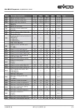
Page 24: ... 24 6 3276 8 3276 7 MA S PS04 Condenser input temperature 24 6 3276 8 3276 7 MA S PS05 Condenser output temperature 24 6 3276 8 3276 7 MA S PS06 Enable analogue output simulation NO 0 NO 0 YES 1 MA S PS07 Evaporator mixing valve 0 0 100 MA S PS08 Condenser mixing valve 0 0 100 MA S PS09 Enable digital output simulation NO 0 NO 0 YES 1 MA S PS10 Switching valve DO1 OFF 0 OFF 0 ON 1 MA S PS11 Switch...

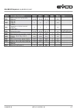
Page 25: ... E PE04 Evaporator valve integral heating time 0 0 999 Sec IS E PE05 Evaporator valve minimum opening output activation step 0 0 PE06 IS E PE06 Evaporator valve maximum opening 100 PE05 100 IS E PE07 Evaporator valve polarity 0 0 10 V 1 10 0 V 0 0 1 IS E PE08 Evaporator valve cooling differential 10 0 0 1 20 0 C IS E PE09 Evaporator valve integral cooling time 0 0 999 Sec IS E PE10 Kind of regulat...

Page 26: ...S S PA07 Condenser low temperature alarm differential 5 0 0 1 20 0 C IS S PA08 Condenser high temperature alarm setpoint 65 0 PA06 70 0 C IS S PA09 Condenser high temperature alarm differential 5 0 0 1 20 0 C IS S PA10 Enable RTC alarm NO 0 NO 0 YES 1 IS S PA11 Type of RTC alarm re arm 0 Automatic 1 Manual 0 0 1 IS S CAN network PH09 CAN network local node 1 1 127 IS CAN PH10 CAN Baud rate 1 20 KB...

Page 27: ...ature unit of measurement 0 Celsius 1 Fahrenheit 0 0 1 IS V PH04 Delete alarm history NO 0 NO 0 YES 1 IS V Set YES 1 and wait for the NO value 0 PH05 Minimum value summer setpoint Cooling 10 0 15 0 PH06 C IS V PH06 Maximum value summer setpoint Cooling 40 0 PH05 70 0 C IS V PH07 Minimum value winter setpoint Heating 40 0 15 0 PH08 C IS V PH08 Maximum value winter setpoint Heating 70 0 PH07 70 0 C ...

Page 28: ... HPRU or CHILLER in order to set the correct MODBUS slave communication Temperature regulation in the neutral zone and MODBUS communication will be inhibited until the type of application of all the slaves configured by the PG01 parameter has been read If the application does not read the type of application of one or more slaves the programme will continue to interrogate the address register ever...

Page 29: ...ill have no effect The application which decides the regulation probe to use will interrogate the slaves in a register called MODBUS to find out if they are reversible or non reversible As regards HPRU slaves the kind of condenser set by parameter PF60 will be taken into consideration if PF60 0 air or PF60 2 water the machine is reversible if PF60 1 water the machine is not reversible For CHILLER ...

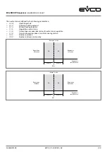
Page 30: ...decrease Regulation increase Regulation increase Regulation temperature Regulation temperature The neutral zone is defined by the following parameters MOdE Operating mode SEtC Summer cooling setpoint SEtH Winter heating setpoint Pr01 Regulation neutral zone Pr02 Percentage increase decrease of neutral zone regulation Pr03 Time increase decrease of neutral zone regulation PG01 Number of slaves PG02...

Page 31: ...ve configured slaves may be in one of the following status 1 Disabled the slave has not been configured in the system 2 Alarm a blocking alarm has occurred in the slave so it is not available for regulating the sequencer 3 Off the slave is off and is not available for regulating the sequencer 4 Ready the slave is available and ready for regulation 5 Active the slave is currently regulated by the s...

Page 32: ...se until the request becomes greater than the minimum value then it will be kept at a minimum until the request is it will not go to 0 For both the valve analogue outputs it is possible to set 0 10 V or 10 0 V polarity using the following parameters PE07 for the evaporator PC07 for the condenser The evaporator mixing valve is based on the following parameters and operates differently according to ...

Page 33: ...ing mode SEtH Winter heating setpoint PG04 Enable condenser mixing valve Pr05 Inversion mixing valves inputs outputs in heating mode PC01 Condenser valve regulation probe PC02 Condenser valve cooling setpoint PC03 Condenser valve cooling differential PC04 Condenser valve integral cooling time PC05 Condenser valve minimum opening activation step PC06 Condenser valve maximum opening PC07 Condenser v...

Page 34: ...larm LED will start flashing Press the ENTER key on the alarm menu to view the code of the first active alarm Once the situation that triggered the alarm has been resolved the alarm can be re armed manually as follows go to the page of the alarm to be reset hold down the ENTER key for about 2 seconds If there are no other active alarms The page with the words NO ALARMS will be displayed The alarm ...

Page 35: ... Evaporator input temperature probe Automatic Inhibits regulation dependent on it Can be set AL13 Evaporator output temperature probe Manual Inhibits regulation dependent on it If regulation probe i turns off all the devices and chnges the status of the sequencer in OFF by alarm Can be set AL14 Condenser input temperature probe Automatic Inhibits regulation dependent on it Can be set AL15 Condense...

Page 36: ...ducer circuit 1 AL32 High pressure transducer circuit 2 AL41 Low pressure transducer circuit 1 AL42 Low pressure transducer circuit 2 AL51 Low pressure start up circuit 1 AL52 Low pressure start up circuit 2 AL61 Compressor discharge gas high temperature circuit 1 AL62 Compressor discharge gas high temperature circuit 2 AL81 Evaporator antifreeze circuit 1 AL82 Evaporator antifreeze circuit 2 AC21...

Page 37: ... or when different types of condenser have been configured in the same network as in the case of slaves with an air condenser together with slaves with a water condenser This alarm will be bypassed when switching on and after a 60 second re arm to enable all the MODBUS registers in the network to be correctly read The consequences of manual re arm alarm are Inhibition of temperature regulation Inh...

Page 38: ...ial of the condenser set by parameter PA06 and PA07 respectively will be used to control this alarm T input T output Low temperature alarm Evaporator low temperature alarm Evaporator high low temperature alarm If the value of the evaporator input or output temperature exceeds the setpoint set by parameter PA04 the evaporator high temperature alarm will be signalled AL07 This is an automatic re arm...

Page 39: ...units are reversible and in heating mode the setpoint and high temperature differential of the evaporator set by parameters PA04 and Pa05 respectively will be used to control this alarm T input T output High temperature alarm High condenser temperature alarm If the value of the condenser input or output temperature falls below the setpoint set by parameter PA06 the condenser low temperature alarm ...

Page 40: ...ice 2 Compliance RoHS 2011 65 EC WEEE 2012 19 EU REACH EC Regulation no 1907 2006 EMC 2014 30 EU LVD 2014 35 EU Power supply 115 230 VAC 10 15 50 60 Hz 3 Hz max 10 VA Earthing methods for the control device None Rated impulse withstand voltage 4 KV Over voltage category III Software class and structure A Clock Built in secondary lithium battery Clock drift 60 s month at 25 C Clock battery autonomy...

Page 41: ...relay 5 A res at 250 VAC The device guarantees reinforced insulation between each digital output connector and the rest of the components of the device Type 1 or Type 2 actions Type 1 Additional features of Type 1 or Type 2 actions C Displays 320x240 px with LCD colour graphic display Communications ports RS 485 MODBUS MASTER INTRABUS USB ...

Page 42: ...he Italian Intellectual Property Rights Code CPI EVCO imposes an absolute ban on the full or partial reproduction and disclosure of the content other than with the express approval of EVCO The customer manufacturer installer or end user assumes all responsibility for the configuration of the device EVCO accepts no liability for any possible errors in this document and reserves the right to make an...

Reviews: