EVCO S.p.A.
Vcolor 869/879
| Installer manual ver. 2.2 | Code 144VC869E214
page 68 of 94
15
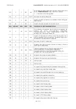
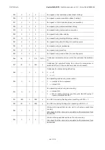
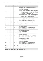
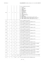
LIST OF CONFIGURATION PARAMETERS
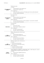
The following table gives the meaning of the configuration parameters.
N.B.
Because some functions are managed according to the value set for some parameters, ensure these are set
correctly and consistently.
PAR.
DEFAULT
MIN.
MAX.
U.M.
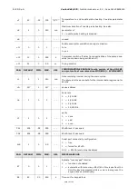
ANALOGUE INPUTS
CA1
0
-25
25
°C/°F
(1)
Cabinet probe calibration
CA2
0
-25
25
°C/°F
(1)
Evaporator probe calibration (if P4=1)
CA3
0
-25
25
°C/°F
(1)
Condenser probe calibration (if P5=1)
CA4
0
-25
25
°C/°F
(1)
Needle probe 1 calibration
CA5
0
-25
25
°C/°F
(1)
Needle probe 2 calibration (if P9>1)
CA6
0
-25
25
°C/°F
(1)
Needle probe 3 calibration (if P9>1)
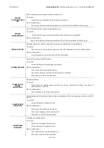
P0
0
0
1
- - - -
Type of probe
0 = PTC
1 = NTC
P2
0
0
1
- - - -
Temperature measurement unit
0
=
°C
1
=
°F
P3
1
0
3
- - - -
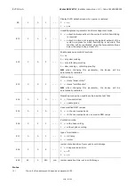
Type of needle probe
0
=
not enabled
1
=
single probe
2
=
multineedle probe
3
=
multi-sensor probe
See also P9
P4
1
0
1
- - - -
Enable evaporator probe
0 = no
1 = yes
P5
1
0
1
- - - -
Enable condenser probe
0 = no
1 = yes
P9
3
1
3
- - - -
If P3=1, P9 must be set to 1
If P3=2, the number set for P9 corresponds to the number of
needle probes present (from 1 to 3)
If P3 = 3, the number set for P9 corresponds to the number of
sensors in the needle probe


