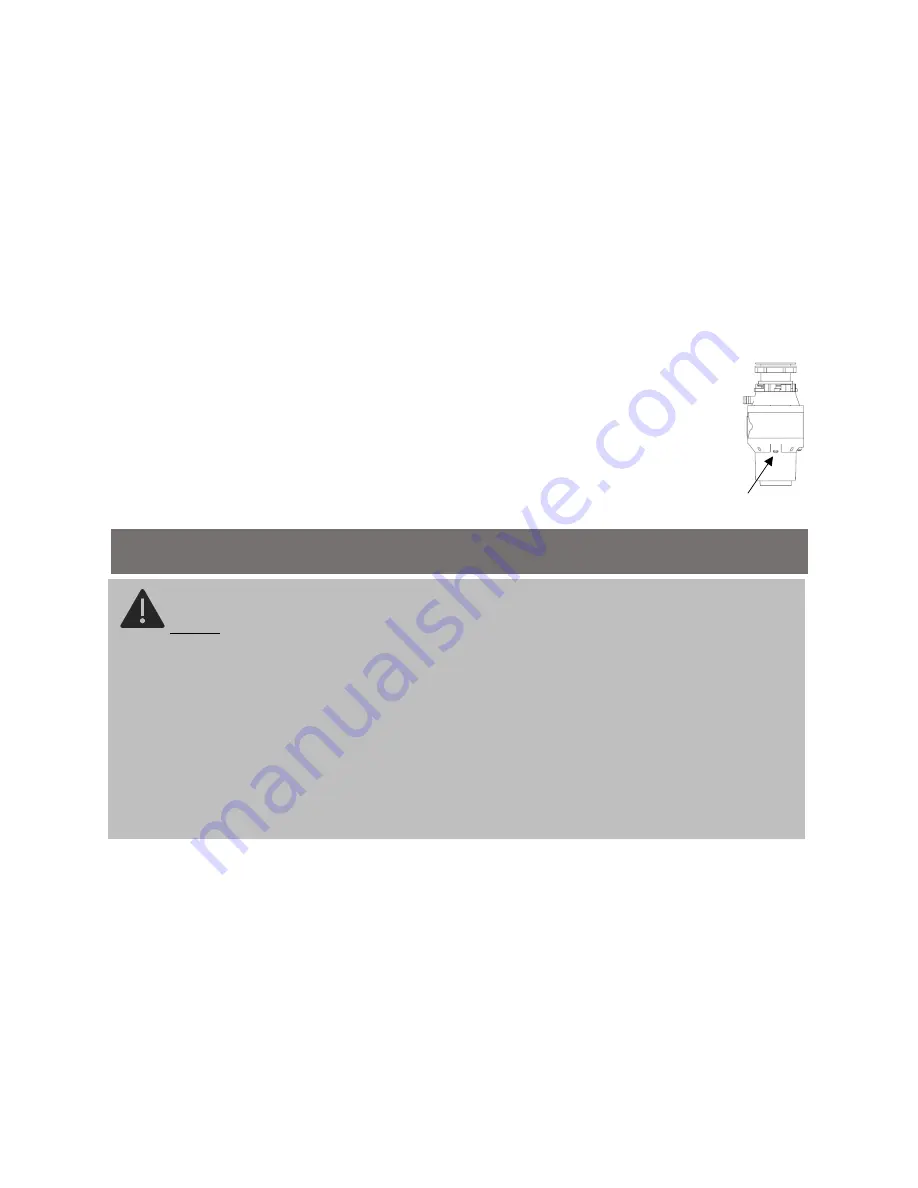
air switch connection point
If you need install wall switch
(
not included
)
, you must do logo for on
/
off, and shall be installed by qualified professionals
.
Wall switch
should be located convenient location on the work surface, separation of contact between the two blades at least 3 mm
.
Using a 20
amp grounded wall socket
.
◎
Air switch
Processor includes built
-
in air switch, air switch by sending a general to control box to activate
/
deactivate the device
.
◎
Air switch installation
1
.
Find the most convenient place on the kitchen table or the sink corners to drill a 33 mm hole
.
Some water tank may be appropriate
with a hole, take off the lid to reveal
.
2
.
Remove the nut on the air switch, let the rubber gasket to stay in place, connect one end of the air tube inserted into the nozzle at
an air switch thread, the other end through the hole of the operating table
.
3
.
To remove the nut back on the air switch, and then screw down the nut below the work station
.
4
.
Picked up the other end of the air duct, insert it tightly into the nozzle of the air switch, the nozzle is located in the
bottom of the processor
Read all operating and safety instructions in instructions
.
Finally, plug the plug tightly in the sink, filled with water in the sink, remove the plug and check whether there is any
leakage on the connection
INSTALLATION
DANGER
:
•
This appliance must be installed by a qualified electrician
•
Improper connection of the equipment
-
grounding conductor can result in a risk of electric shock
.
Check with a
qualified electrician or serviceman if you are in doubt as to
whether the appliance is properly grounded
.
.
•
DO NOT DISASSEMBLE THIS PRODUCT
•
Our company reserves the right not to be responsible for any loss, damage or any types of injury as a result of
improper installation, misuse of the product or the owner
’
s inability to maintain the product
in a good / functioning
condition
Summary of Contents for FWD560+
Page 1: ...Food Waste Disposer FWD560 Instruction Manual...
Page 2: ...o o o o o o o o reset...
Page 4: ...A B C D sink E...
Page 5: ...F G H...
Page 6: ...90 1 2 ADAPTER adapter 3 90 90 90...
Page 8: ...SINGLE BOWL DOUBLE BOWL 1 230 300 2...
Page 9: ...1 2 3 4 15 15...
Page 10: ...reset reset reset 90 overload control reset...
Page 11: ...1 2 3 O ring...


