background image

__________________________________________________________________________________________________________________ 

Series GA201-M2 

15 

LT126 June 2021 

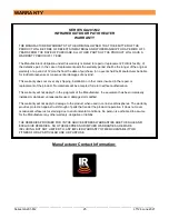
3.  Locate the regulator assembly. Look over the assembly to make sure no damage has occurred during shipping 

or handling. Attach the regulator assembly to the male quick connect on the fuel supply hose as shown in 

Figure 10. 


Figure 10:  Connect Regulator Assembly to Fuel Supply Hose 


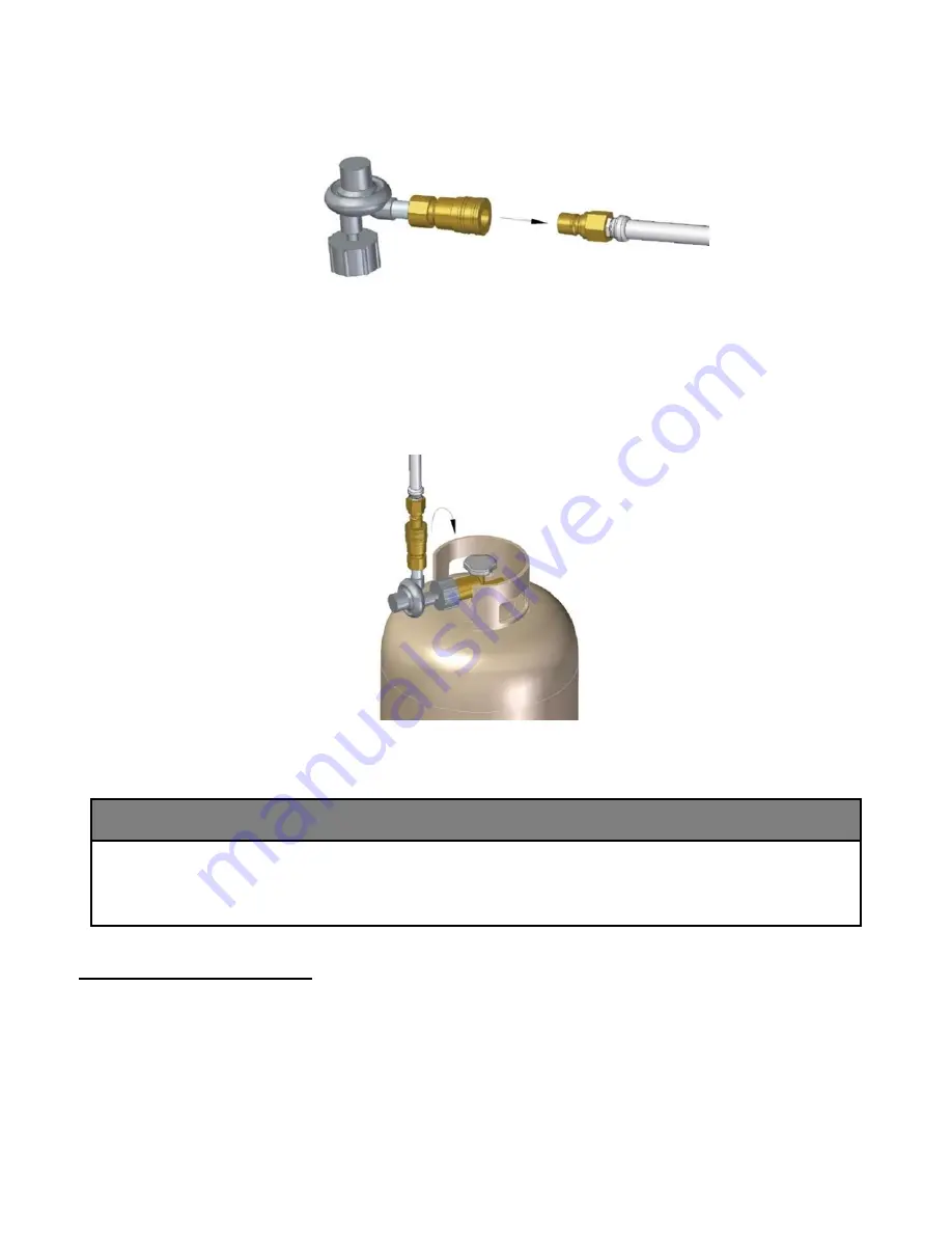
4.  Secure the Gas Hose Regulator onto the Propane-Gas cylinder valve by turning the Regulator clockwise until 

tight. Push the 2 spring latches that are holding the main housing cover in place inwards, one hand holding the 

bottom lip of the main housing cover and the other one pushing the latches one at a time. Be careful of the 

bottom edge of the main housing as it is sharp. 


Figure 11:  Secure Gas Regulator to Propane Cylinder 


CAUTION


Before using the patio heater:


  Perform a leak test to make sure the regulator connection does not have leaks.


  Move heater to desired location. 

  Secure the Base Body to the floor (optional). 


Position / Move Heater 


1.  Ensure the Propane-gas Cylinder is turned 

OFF

, secured and disconnected from the Gas Hose prior to 

moving the Heater. 


2.  Ensure the wheels are properly connected to the base body (refer to installation step 8). 


Summary of Contents for GA201M2

Page 1: ...Improper installation adjustment alteration service or maintenance can cause injury death or property damage Read the installation operation and maintenance instructions thoroughly before installing o...

Page 2: ...CLEARANCE TO COMBUSTIBLE MATERIALS 8 INSTALLETION INSTRUCTIONS 9 SHIPPING CRATE CONTENTS 9 HARDWARE KITS 10 ASSEMBLY 10 CONNECTING THE GAS SUPPLY 14 POSITION MOVE HEATER 15 SECURE THE HEATER OPTIONAL...

Page 3: ...o the hazards of high surface temperatures and should stay away to avoid burns or clothing ignition Young children should be supervised when they are in the area of the heater Playing or running aroun...

Page 4: ...cted prior to moving the Heater Storage of a Heater indoors is permissible only if the Propane Gas Cylinder is disconnected and removed from the Heater Use caution when moving the Heater it may requir...

Page 5: ...equipment and can be called upon for helpful suggestions about installation APPLICABLE REGULATIONS Installation must comply with local building codes or in their absence the latest edition of the app...

Page 6: ...ich includes an overhead cover and no more than two side walls These side walls may be parallel as in a breezeway or at right angles to each other 3 Within a partial enclosure which includes an overhe...

Page 7: ...a described in the Installation Codes section of this manual The Cylinder and its connector fittings must be maintained in good condition High Altitude Installation When installing this heater over 45...

Page 8: ...ustible materials are considered to be wood compressed paper plant fibres plastic Plexiglas or other materials capable of being ignited and burned Such materials shall be considered combustible even t...

Page 9: ...______________________________________ Series GA201 M2 9 LT126 June 2021 INSTALLATION INSTRUCTIONS Shipping Crate Contents Base with Case Cover Pole and Counterweight QTY 1 Heater Head with Gas Hose Q...

Page 10: ...1 4 S S Lock Washer x2 EH089 Used to Secure Pole Assembly to Base Body o 3 8 16 S S Nylon Lock Nuts x6 o 3 8 S S Washers x6 o 3 32 Allen Key o 1 8 Allen Key Reflector EH001 Used to Secure Reflector t...

Page 11: ...3 2 Remove the screws from the burner head assembly 4 screws Insert the gas supply hose into the pole neck The hose will slide down the pole until the head assembly sits in the pole neck Figure 3 Hea...

Page 12: ...is not shown below for ease of illustration Figure 5 Pole and Housing Assembly 6 Take the contents out of hardware bag EH089 Slip the washers on the threaded bolts 6 washers Secure the pole assembly...

Page 13: ...ort arms and then through the top reflector Secure each bolt on top of the reflector Note Make sure to remove or peel off the plastic covering on the reflector before assembly Figure 7 Attach Top Refl...

Page 14: ...Dangerous Goods and Commission CAN CSA B339 TC approved in Canada 1 Lift the Main Housing Cover up by the handles until the bottom lip is clear of the 2 spring latches as shown below Figure 8 Lift Mai...

Page 15: ...l tight Push the 2 spring latches that are holding the main housing cover in place inwards one hand holding the bottom lip of the main housing cover and the other one pushing the latches one at a time...

Page 16: ...Optional 1 Ensure that the Hold Down Brackets are properly installed as described in Installation Step 8 2 The type of Foundation Fastener required depends on the type of Floor Ground that the Heater...

Page 17: ...linder valve ON Check the connections at the Propane Gas cylinder 4 Take off the Housing Service Cover see Figure 12 Check the gas line attachment points to the valve 5 Any leaks will result in bubble...

Page 18: ...acing the Battery 1 Remove the Housing Service Cover to access the Ignitor Module Knob 2 Turn the ignitor module knob counter clockwise to unscrew it 3 Pull out the battery while taking note of the po...

Page 19: ...ting a longer interval before releasing the knob Note When using the heater with a fresh fuel supply pilot may take some time to light because the light needs to purge all the air out of the line firs...

Page 20: ...d cobwebs 4 Visually check the Burner flame pattern during use A Proper Flame should resemble image on Figure 16 5 If at any time flames extend beyond the emitter surface see image in Figure 17 Improp...

Page 21: ...detergent is sufficient Next in order mild non scratching abrasive powders such as typical household cleaners These can be used with warm water bristle brushes sponges or clean cloths DO NOT USE ordi...

Page 22: ...time to light because the light needs to purge all the air out of the line first No Spark Ensure the battery in ignition module is operating Ensure spark electrode assembly is grounded and there are...

Page 23: ...168 1 12 Tip Switch RP EE034 1 13 Electronic Igniter RP EE028 1 14 Gas Valve RP EG036 1 15 Current Interrupter RP EG038 1 16 Pilot Burner RP EE032 1 17 Thermocouple RP EE038 1 18 Breakaway Pilot Nut K...

Page 24: ...__________________________________________________________________________________________________________________ Series GA201 M2 24 LT126 June 2021 Part Reference...

Page 25: ...does not cover any shipping installation or other costs incurred in the repair or replacement of the product No materials will be accepted for return without authorization This warranty will not appl...

Reviews: