DIR911T User Guide
81
Figure 65: Rear Panel Connector Locations
Figure 66: Rear Panel Connector Locations
Each of the individual connectors is described in the subsections that follow.
Power Input Connector
There is a 2.1mm DC barrel type connector on the rear panel that provides DC power to
the unit. This should only be connected to the DC power supply provided with the unit.
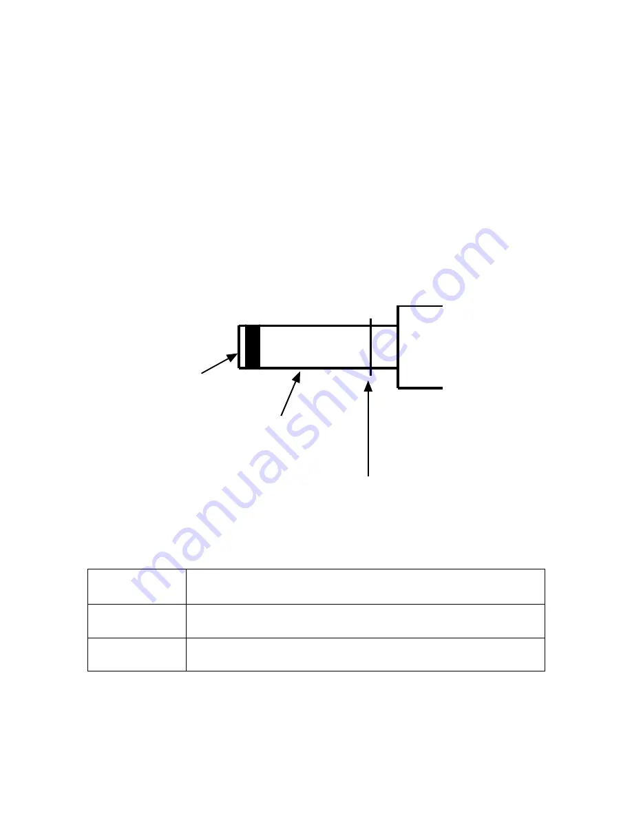
The mating connector for this jack is shown in Figure #67 and the pin description is
shown in Table #14.
Inner
Outer
Locking Flange
Figure 67: Rear Panel DC Power Connector Pin Diagram
Pin
Description
INNER
+12V at 1.5A
OUTER
Ground
Table 14: Rear Panel DC Power Connector Pin Description
Summary of Contents for DIR911t
Page 2: ......
Page 16: ......
Page 18: ......
Page 21: ...DIR911T User Guide 21 Figure 1 Front Panel Diagram A B C D E F G H I K J M L N O P Q R S ...
Page 25: ...DIR911T User Guide 25 Figure 2 Rear Panel Diagram B A C D E F G H I J K N M L ...
Page 32: ......
Page 68: ......
Page 70: ......
Page 71: ...71 Factory Defaults The Table 8 specifies the factory defaults of the DIR911t ...
Page 90: ......
Page 92: ......


