background image

POWERLINE 11 series UPS – Instruction Manual  


2011/07/22 

www.ever.eu


11 

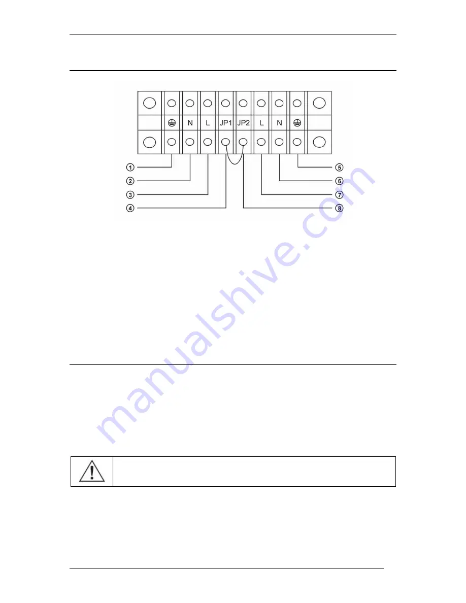
Input / Output Installation 


1 – PE cord of the power supply line 

2 – N cord of the power supply line 

3 – L cord of the power supply line 

4 – Jumper (parallel operation option) 

5 – PE cord of the output line 

6 – N cord of the output line 

7 – L cord of the output line 

8 – Jumper (parallel operation option) 

FIRST START 

When started for the first time the battery back-up may require to be left connected to 

the  mains  in  order  to  allow  the  internal  accumulators  to  charge.  In  order  to  do  this, 

connect the input power supply line. UPS will charge the accumulators regardless of 

the  operation  mode  (ONLINE  –  UPS  on,  inverter  working,  or  OFFLINE  –  UPS  off, 

inverter not working, output powered by the bypass system).  


WARNING!  Back-up's  batteries  reach  their  full  capacity  after 

approximately a month of mains operating mode. 

Summary of Contents for POWERLINE 11 series

Page 1: ......

Page 2: ... MODE 03 MODE 14 STORAGE CELLS TEST MODE 04 MODE 14 SERVICE BYPASS OPERATION MODE 15 EMERGENCY MODE 15 SAFEGUARDS 16 Against overloads 16 Against shorting 16 EPO 17 COMMUNICATION BETWEEN THE UPS AND A COMPUTER 17 RS232 COMMUNICATION 17 WinPower SOFTWARE INSTALLATION 18 Installation on computers with Windows 18 CONFIGURING THE BATTERY BACK UP S PARAMETERS 18 INSTALLATION AND CONFIGURATION OF THE PO...

Page 3: ...h equipment powered by monophase 230V mains WARNING POWERLINE battery back ups were not designed to work with medical equipment in particular life and or health support devices General features of the battery back up POWERLINE battery back ups consist of the following functional units rectifier unit with PFC power factor correction accumulator charger accumulator unit in a battery module inverter ...

Page 4: ... system security In the event of a failure of the inverter the current from the mains will be provided directly to the load Thus the automatic bypass system becomes an additional passive safeguard of the load Additional function of manual connection of the bypass enables a complete switch of the load power supply to mains and thus conducting servicing or maintenance work Internal electronic circui...

Page 5: ...played if the voltage is regular Indicates excessively low input voltage not displayed if the voltage is regular Output Output voltage value Output voltage frequency Load Unit load in W or VA Indicates short circuit of the unit s output Indicates unit overload Storage cells Storage cells voltage value Charge level of storage cells Indicates overload of the storage cells the unit will switch to bat...

Page 6: ... Rear panel view of POWERLINE 6 11 and POWERLINE 10 11 back ups 1 Cover of the power supply and receiver grid connections 2 Cover of the servicing BYPASS switch 3 Input safeguard 4 Parallel port optional 5 Expansion card optional 6 RS232 communications port 7 Fans 8 EPO connector ...

Page 7: ... the device to the mains inspect the condition of power leads plugs and sockets as well as the condition of the device itself To minimise the risk of electric shock in cases when there is no way of verifying the earthing the device should be disconnected from the mains before installation or connection of other equipment to the back up reconnect the power cord only after all connections are made i...

Page 8: ... emergency power off EPO located near the main power switch and appropriately marked WARNING Users are forbidden to carry out any maintenance activities as they may lead to injury or death Any repairs and replacement of batteries should be conducted only by a qualified representative of the technical support WARNING The battery back up is disconnected from the mains only when the power cord is rem...

Page 9: ...ARNING The device is delivered with its accumulator connected The battery back up is packed in a manner enabling safe transport including by forklift truck To unpack the device carefully cut the protective bands slide the cardboard cover off remove the foam safeguards according to H S instructions remove the battery back up from the wooden transport pallet this may require assistance place the bac...

Page 10: ...should be kept according to the guidelines technical parameters table CONNECTING THE BATTERY BACK UP The connection should meet the requirements concerning the cable cross sections and installed safeguards cf technical parameters table WARNING Connecting of the battery back up to the mains should be performed only by a qualified and authorised personnel WARNING The battery back up is disconnected ...

Page 11: ...r parallel operation option FIRST START When started for the first time the battery back up may require to be left connected to the mains in order to allow the internal accumulators to charge In order to do this connect the input power supply line UPS will charge the accumulators regardless of the operation mode ONLINE UPS on inverter working or OFFLINE UPS off inverter not working output powered ...

Page 12: ...attery in the wide range of input voltages 176 276 V providing the 230 V voltage to the receivers Another advantage of constant processing in ONLINE class back ups is that there is no interruption when switching the load to another power supply mains battery Switching between mains and battery operation modes are imperceptible for the receivers connected to the UPS output Code Operational status I...

Page 13: ...e of overload or exceeding the acceptable temperature then it will automatically conduct periodical examinations of the load and the inverter s temperature When the above values return to normal levels the inverter is reconnected In BYPASS mode the unit does not provide any protection against voltage decay Voltage from the input line is switched to the unit s output through an internal filter MAIN...

Page 14: ...connecting the input power supply line BACK UP BATTERY OPERATION MODE 03 MODE In the back up operation mode the true sine wave output voltage is generated by the accumulator until the mains voltage returns the accumulator is discharged or an emergency situation takes place In the event of no mains voltage the unit is activated in the same way as in mains operation mode however the difference is th...

Page 15: ...wer from the receivers plugged into the UPS output WARNING In the service BYPASS operation mode the receivers powered by UPS output are in no way protected from power loss in the mains In this mode the UPS is completely disconnected from the output EMERGENCY MODE In this mode the unit sends the appropriate error codes to the LCD panel and emits sound signals as per the following table ...

Page 16: ... Damaged battery thyristor Continuous sound signal 15 Parallel operation errors Continuous sound signal 22 Incorrect fan operation A single sound signal every 1 second 23 Damaged batteries and loader A single sound signal every 1 second SAFEGUARDS Against overloads An overload condition is signalled by the relevant code on the LCD panel and a sound signal cf Table 1 If the overload reaches 105 130...

Page 17: ...ort circuit in the EPO circuit has been rectified the unit may be powered on using the standard procedure The EPO connector pins have a safe voltage that is separated from the remaining systems of the device NOTE The EPO circuit must be a separate circuit and it is forbidden to connect it to other systems COMMUNICATION BETWEEN THE UPS AND A COMPUTER RS232 COMMUNICATION POWERLINE series battery bac...

Page 18: ...omputer with Windows just run the software installer and follow the instructions onscreen WARNING When the software prompts for a serial number please key 511C1 01220 0100 478DF2A CONFIGURING THE BATTERY BACK UP S PARAMETERS WinPower allows the user to change certain parameters of the battery back up To make it possible the battery back up must be connected to the computer with the cable provided ...

Page 19: ...to install PowerSoft on a computer with Windows the list of operating systems compatible with the application is available at www ever eu just run the software installer and follow the instructions onscreen During the installation you will be asked to select the model of the battery back up connected to the computer on which the software is being installed This setting may also be changed when the...

Page 20: ...rking with the PowerSoft must have root privileges to install the software and use it After installation the application may be found in the usr local powersoft directory To uninstall the application enter the following command rpm ev powersoftpersonal x x x Debian For the Debian systems the software is provided in the form of a DEB package The software is installed via the following command dpkg ...

Page 21: ...otify the user when updates are available By default the software check for updates after user log in This setting may be changed in the Update configuration item in the system s programme menu Linux Unix systems In the case of Linux Unix systems PowerSoft may be updated by downloading the new package from www ever eu In the case of CentOS RedHat Suse Linux and Fedora Core Powersoft may be updated...

Page 22: ...r of the protected equipment does not exceed the range of powers accepted by the battery back up the equipment will cause the UPS to shut down This happens because the protected equipment temporarily draws power that significantly exceeds the nominal power of the battery back up which causes a detection of an overload and the resulting shutdown This situation may take place in the following cases ...

Page 23: ...be charged every 6 months In temperature between 30 C and 45 C the accumul ator should be charged every 3 months DISPOSAL Appropriate disposal of used up electric and electronic equipment helps to avoid consequences resulting from the presence of dangerous materials as well as inappropriate storage and processing of such equipment which may be hazardous to human life and the environment Act dated ...

Page 24: ... 10 mm2 16 mm2 Line safeguards 2 x 50 A chk C 2 x 80 A chk C OUTPUT PARAMETERS Output system layout 1P3W Nominal output voltage 230 V Nominal output current 19 A 31 A Max output current 45 A 74 A Min cable cross section 10 mm2 16 mm2 Line safeguards 2 x 50 A chk B 2 x 80 A chk B ENVIRONMENTAL PARAMETERS Amount of heat radiated in nominal operating conditions 1500 BTU 2400 BTU Operating temperature...

Page 25: ...t time 100 80 50 Pmax 9 12 28 min 6 8 20 min Accumulator 20 x VRLA 12V 7 Ah 20 x VRLA 12 V 9 Ah Maximum charging time of internal batteries 5 h MECHANICAL PARAMETERS Dimensions h x w x d 717 x 260 x 570 mm UPS weight 90 kg 93 kg Battery module weight N a EQUIPMENT Outlet sockets Power rack Signalling LCD panel sound signals Cut out 2 x 50 A D circuit breaker protection at the mains side Communicat...

Page 26: ...continuous sound signal Receiver overload or short circuit Check the receivers and disconnect non critical receivers Recalculate the power load and reduce the number of receivers connected to the unit Check whether any of the receivers are damaged Warning code 23 sound signal every 1 second Damaged storage cells or loader Contact technical support Error code 11 continuous sound signal Low charge l...

Page 27: ...to how the defect is removed The warranty does not cover devices with mechanical damages that occurred as a result of negligence of incorrect use nor devices subjected to any modifications made by the user Apart from the arrangements included in the warranty card EVER Sp z o o does not grant any guarantee or warranty including warranty of merchantability or fitness for particular purpose Apart fro...

Reviews: