EVER POWERLINE RT PLUS UPS Operating Manual
2019-11-25 11:43
Technical Support, phone: +48 61 6500 400
14
BATTERY MODULE DESIGN
– REAR PANEL
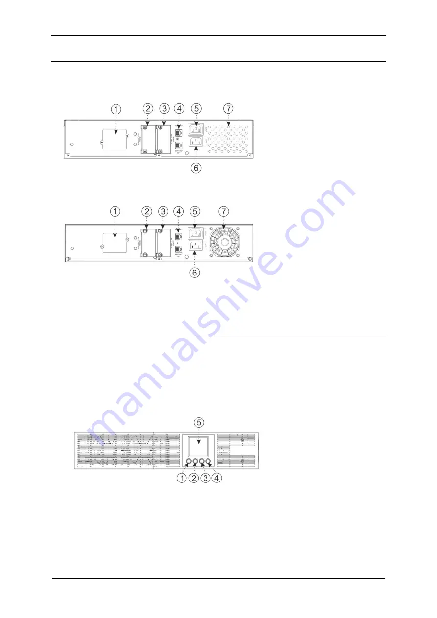
Figures 4 - 5 present the elements found in rear panels of battery modules for
POWERLINE RT PLUS units.
1. Fuse compartment cover
2. Cover of the battery module
output terminal
3. Cover of the battery module input
terminal
4. RJ45 / RJ11 port
– battery
module detection
5. Output socket supplying power to
the internal charger of the
consecutive battery module
6. Socket supplying power to the
internal charger of the
consecutive battery module
7. Air vents / fan
Fig. 4: View of the rear panel of the battery module for
POWERLINE RT 1000
Fig. 5: View of the rear panel of the battery module for
POWERLINE RT 2000 - 3000
HOW IT WORKS
The UPS unit comes with an LCD display with four buttons. Fig. 6 shows front panel
elements of the POWERLINE RT PLUS unit, along with their description. Table 1
presents the description of the buttons of the control panel and Table 2 presents the
description of audio signals indicating the unit's various operation states.
1. Start button (ON)
2. Shut down button (OFF)
3. Confirmation button (ENTER)
4. Exit button (ESC)
5. LCD display
Fig. 6: View of the front panel of the POWERLINE RT PLUS 1000 unit
Summary of Contents for POWERLINE RT PLUS 1000
Page 1: ......


