background image

SINLINE series UPS – Instruction Manual  

2010/01/26


www.ever.eu


23 

ADDITIONAL REMARKS 


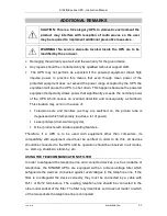
CAUTION: This is a C2-category UPS. In domestic environment the 

product  may  interfere  with  reception  of  radio  waves  so  the  user 

may be required to implement additional preventive measures. 


WARNING!  No  service  elements  located  inside  the  UPS  are  to  be 

modified by the end user. 

  Damaging the warranty seal will void the warranty for the given device. 

  Any repairs should be conducted only by qualified technical support staff. 

   The  UPS  may  not  perform  as  expected  if  the  powered  equipment  draws  high 

impulse  power.  In  practice  this  means  that  even  though  mean  power  of  the 

protected equipment does not exceed the power range accepted by the UPS, the 

equipment will cause the UPS to shut down. This happens because the powered 

equipment temporarily draws power that significantly exceeds the nominal power 

of  the  UPS,  which  causes  an  overload  detection  and  consequently  a  shutdown. 

This situation may occur in the case of: 

  Television  sets  and  monitors  (as  they  are  switched  on,  the  picture  tube  is 

degaussed which temporarily requires a lot of power),  

  Laser printers (drum warming cycle), 

  Other products with similar operating features. 

Therefore,  if  a  UPS  is  to  be  used  with  equipment  other  than  computers,  its 

compatibility  with  equipment  used  must  be  verified.  In  order  to  do  this,  all  devices 

should be connected to the UPS and its operation should be observed in all modes, 

i.e. start-up, shutdown, stand-by, etc.. 

USING THE TELECOMMUNICATIONS FILTER 

In order to safeguard the telephone line and connected devices, such as modems or 

telephones,  the  SINLINE  UPSs  are  equipped  with  an  anti-overvoltage  filter  which 

safeguards  the  devices  connected  against  overvoltages  in  the  telephone  line.  If  the 

filter  is  to  safeguard  the  device  correctly,  they  must  be  connected  by  a  cable  with 

RJ11  or  RJ12  terminators.  The  existing  telephone  line  should  be  connected  to  the 

other outlet socket of the filter. The filter is symmetrical, so it does not matter to which 

of the two sockets the telephone line is connected. 

Summary of Contents for Sinline 1200

Page 1: ......

Page 2: ... 12 FIRST START 15 DESCRIPTION OF THE UPS S OPERATION 16 GENERAL INFORMATION 16 MAINS OPERATION MODE 17 BATTERY MODULE BATTERY OPERATION MODE 17 SAFEGUARDS 18 COMMUNICATION BETWEEN THE UPS AND THE COMPUTER 19 INSTALLATION AND CONFIGURATION OF THE POWERSOFT PERSONAL SOFTWARE 20 Installation on computers with Windows 20 Installation on computers with Linux Unix 20 Software Updates 21 CONFIGURING THE...

Page 3: ...UPSs are LINE INTERACTIVE class devices designed to work with equipment powered by monophase 230V mains In battery module operation mode they generate true sine wave voltage at their output This enables a much wider range of tolerated loads when compared with power supply devices using approximation of the sinusoid UPSs belonging to this group may power virtually any device whose power does not ex...

Page 4: ...battery module such as shape of the output voltage frequency of the output voltage charge level of batteries Digital monitoring of external parameters such as value of the mains voltage frequency of the mains voltage value of the output voltage value of the output current value of the power connected to the battery modules output AVR Automatic Voltage Regulation automatic mains voltage regulation ...

Page 5: ...gle battery at which individual LEDs light up 2 Power switch 3 LED indicating whether the AVR Automatic Voltage Regulation system is active 4 Two colour LED indicating the operation mode a Mains operation mode constant green light b Battery module operation mode constant yellow light 5 A column of LEDs three green top one red indicating the percentage load of the UPS The top red LED indicates that...

Page 6: ...output If only the red LED is lit with acoustic signal it indicates that the battery module has overloaded REAR PANEL Fig 2 Rear panel 6 Outlet sockets 7 RS232 serial port for communication with a PC 8 Telecommunications filter sockets 9 Power cord 10 Circuit breaker fuse in battery modules with power of 800VA 1200VA and 1600VA circuit breaker in battery modules with power of 2000VA and 3000VA ...

Page 7: ... active 5 A line of LEDs three green and one red indicating the percentage load of the UPS The red LED indicates that the BACK UP Sload exceeds the recommended nominal power level If only the red LED is lit and blinking quickly with acoustic signal it indicates the occurrence of a short circuit at the BACK UP Soutput If only the red LED is lit with acoustic signal it indicates that the battery mod...

Page 8: ...0 C13 outlet sockets 8 RS232 serial port for communication with a PC 9 Power cord socket 10 Telecommunications filter sockets HEALTH AND SAFETY INSTRUCTIONS HANDLING exercise utmost caution when handling the device do not handle heavy equipment by yourself storage and operation of the device should take place in conditions conforming to its specification ...

Page 9: ...lugged in to a 3 lead socket two poles and earthing connecting the device to any other socket may result in electric shock The device receiving the current must be connected with an appropriate circuit protection manual circuit breaker or circuit breaker A device powered via a cord with a plug has an earthing lead that carries away the leakage current from the receivers e g computer equipment the ...

Page 10: ...guide RS232 communication cable to connect the battery module to a computer warranty card backup fuse only for Sinline Tower model backups with the power of 800 VA 1200 VA and 1600 VA 2 moving handles for cabinet installation Rack Model only INSTALLATION OF THE SINLINE UPS Tower Model When choosing the installation location you must take the device s weight into account The battery module should o...

Page 11: ...ed The battery module is designed for installation in a cabinet rack To facilitate installation in cabinets racks of various depth the device is equipped with moving handles which enable installation in racks with depth of up to 600 mm If the battery module is to be installed in a rack of 800 mm or 1000 mm depth it is possible to order longer handles to adjust the product for installation in such ...

Page 12: ...y of flammable materials CONNECTIONS The mains socket the UPS is to be connected to should be located near the battery module maximum distance 1 5 m and should be easily accessible Do not use additional extension cords to connect the device to the mains WARNING The UPS is disconnected from the mains only when the power cord is removed from its socket ...

Page 13: ...ze of load connected to the installation Differing characteristics of protections of installations in the building and the UPS may in extreme cases lead to quicker responses of the former Input installation To connect the UPS in accordance with the instruction manual the layout of terminals of the mains socket is important L N PE Fig 7 Layout of terminals of a mains socket The figure below present...

Page 14: ...ectly arranged output connections is presented on the scheme below WARNING The output side of the battery module only allows the TN S mains configuration Fig 9 Output installation of a Tower model Sinline UPS The arrangement of terminals of output sockets of Tower and Rack model Sinline UPS is presented on figures 10 and 11 below L PE N L PE N L PE N L PE N Fig 10 The arrangement of terminals of o...

Page 15: ...atteries can be found in the technical parameters table Afterwards the user may continue with the installation procedure Take the following steps Turn the UPS off switch in the 0 position only if it was turned on connect the devices that require buffer power supply e g computer and monitor to the outlet sockets on the UPS connect the UPS to the computer via the RS232 cable turn on the UPS with the...

Page 16: ...ly conditions without tapping into the energy reserves stored in the batteries In the battery module operation mode the system generates a precisely stabilised output voltage in the shape of sinusoid which enables supplying power to a wide range of equipment that does not tolerate quasi true sine waves The dedicated DPC system monitors the operation of the UPS it has a precise and very quick react...

Page 17: ...ns voltage is incorrect too low or too high voltage or frequency exceeding the operation range the UPS switches to the battery module operation mode and lights the yellow operation mode LED or red in the Rack model In the mains operation mode the UPS s outlet provides mains voltage that was filtered or raised by the AVR system BATTERY MODULE BATTERY OPERATION MODE In the battery module operation m...

Page 18: ...nt is limited to a safe level This is signalled by a quick blinking of the last LED red in the load indication column and a quick intermittent sound signal If the shorting lasts longer than 0 5 second the UPS switches to the emergency operation mode Against overvoltage Devices connected to the UPS are protected against mains overvoltage This solution protects the receivers against impulse current ...

Page 19: ...UPS must be connected to the computer with the provided cable After the cable is connected turn on the battery module start the computer and install the software in accordance with the instruction manual or the instructions provided by the installation software WARNING The communication connection between the UPS and the computer should be made only if the user intends to use the control software ...

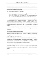
Page 20: ...h the software is being installed This setting may also be changed when the application is running To uninstall PowerSoft select the Uninstall PowerSoft option in Start Menu You can also uninstall PowerSoft from the Add and remove programs menu in the control panel Installation on computers with Linux Unix The binary version of the application for Linux Unix systems is provided in the following fo...

Page 21: ...PowerSoftpersonal x x x tbz To uninstall the application enter the following command pkg_delete PowerSoft Starting the software When the installation is complete the system service is started automatically while the control panel application can be found at usr local PowerSoft Please note that for the English diacritics to be correctly displayed the system locale should be English Software Updates...

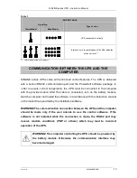
Page 22: ...To enable this the UPS must be connected to the computer with the cable provided by the manufacturer A list of these parameters together with available settings is presented in the table below Table 2 PARAMETER FUNCTION DEFAULT SETTING USER CHOICE DESCRIPTION Acoustic signalling On On Off Only for the battery operation mode Delay before standby mode 90 sec 5 255 sec Time between system shutdown an...

Page 23: ...consequently a shutdown This situation may occur in the case of Television sets and monitors as they are switched on the picture tube is degaussed which temporarily requires a lot of power Laser printers drum warming cycle Other products with similar operating features Therefore if a UPS is to be used with equipment other than computers its compatibility with equipment used must be verified In ord...

Page 24: ... replace the fuse turn the UPS off with the power switch remove the power cord from the socket remove the fuse holder and replace the fuse with a spare one that conforms to the BACK UP Sspecification The holder contains one spare fuse in addition to the one installed DISPOSAL Appropriate disposal of used up electric and electronic equipment helps to avoid consequences of the presence of dangerous ...

Page 25: ... output voltage LC Shorting protection Electronic Overload protection Electronic Time to switch back to mains operation 0 ms Support time 100 80 50 Pmax 5 7 12 min 4 5 6 10 min 4 5 8 min 4 5 9 min 3 4 8 min Battery 2 x 5 Ah 2 x 7 Ah 3 x 5 Ah 4 x 5 Ah 4 x 7 Ah Maximum charging time 5 h 7 h 5 h 5 h 7 h MECHANICAL PARAMETERS Dimensions h x w x d in mm 190 165 480 190 165 640 Weight 14 kg 16 kg 20 kg ...

Page 26: ...oltage 50 Hz 1 Hz Filtering of output voltage LC Shorting safeguard Electronic Overload protection Electronic Time to switch back to mains operation 0 ms Support time 100 80 50 Pmax 4 5 6 10 min 4 5 8 min 4 5 9 min 3 4 8 min Battery 2 x 7 Ah 3 x 5 Ah 4 x 5 Ah 4 x 7 Ah Maximum charging time 7 h 5 h 5 h 7 h MECHANICAL PARAMETERS Dimensions 2U x 19 320 3U x 19 400 3U x 19 400 3U x 19 400 Weight 20 kg...

Page 27: ...urer shall make the decision as to how the defect is removed The warranty shall not cover devices with mechanical damages that occurred as a result of negligence of incorrect use nor devices subjected to any modifications made by the user Apart from the arrangements included in the warranty card EVER Sp z o o shall not grant any guarantee or warranty including warranty of merchantability or fitnes...

Reviews: