background image

SINLINE XL series UPS – Instruction Manual 

2010/01/27


www.ever.eu


19 

DESCRIPTION OF THE BACK-UP’S OPERATION 

GENERAL INFORMATION 

The  SINLINE  XL  UPS  is  a  state-of-the-art  electronic  device  constituting  an 

autonomous source of true sine wave voltage of ~230V. This device belongs to the 

group  of  LINE-INTERACTIVE  (VI)-class  UPSs,  which  includes  UPSs  that 

synchronise with the mains. The UPS is equipped with the CLEAR DIGITAL SINUS 

(CDS) system, which generates a precisely stabilised output voltage in the shape of 

sinusoid, which enables supplying power to a wide range of equipment that does not 

tolerate quasi-sine wave voltages. This system increases the reliability of the device 

and guarantees stable operation of the UPS. 

With  the  help  of  the  Automatic  Voltage  Regulation  (AVR)  system  the  UPS  instantly 

corrects  slight  drops  in  the  mains  voltage  to  provide  the  receivers  with  appropriate 

power  supply  conditions  without  tapping  into  the  energy  reserves  stored  in  the 

batteries.  

The back-up also uses the system of advanced DIGITAL POWER CONTROL (DPC) 

which precisely shapes the oscillation of the output voltage to obtain a clear sinus. In 

the mains  operating  mode  the  system filters the mains  voltage  to  remove  the  noise 

and distortions that may be dangerous for the receivers.  

The dedicated DPC system monitors the operation of the UPS; it has a precise and 

very quick-reacting system of detecting overloads and outlet shorting in the back-up 

operation  mode.  In  mains  operation  mode  the  shorting  safeguard  is  provided  by  

a cut-out and overloads are signalled both visually and acoustically. 

When the UPS is started in the back-up operation mode, a special soft start mode is 

used  in  order  to  launch  with  high  loads  that  draw  high  starting  current,  e.g.  laser 

printers. 

Moreover,  the  DPC  system  enables  long  operation  in  battery  mode  by  allowing 

connection  of  an  additional  battery  module  and  control  of  internal  temperature  by 

means of an active cooling system, which is activated as necessary. This manner of 

switching on the cooling reduces the amount of noise generated by the UPS.  

The DPC system offers various modes of communication between the UPS and the 

computer via a communication port or a special slot for the Ever management card 

(HTTP, telnet, SNMP). 

Summary of Contents for SINLINE XL 1800

Page 1: ......

Page 2: ...14 Installing themanagement card 15 CONNECTING THE UPS 15 Input installation 16 Output installation 17 FIRST START 18 DESCRIPTION OF THE BACK UP S OPERATION 19 GENERAL INFORMATION 19 MAINS OPERATION MODE 20 BACK UP BATTERY OPERATION MODE 20 STAND BY MODE 21 EMERGENCY MODE 21 SAFEGUARDS 22 COMMUNICATION BETWEEN THE UPS AND THE COMPUTER 23 COMMUNICATION VIA RS232 OR USB 23 INSTALLATION AND CONFIGURA...

Page 3: ...for work with equipment powered by monophase 230V mains In back up operation mode they generate true sine wave voltage at their output This enables a much wider range of tolerated loads when compared with power supply devices using approximation of the sinusoid UPSs belonging to this group may power virtually any device whose power does not exceed the nominal power of the UPS SINLINE XL UPSs do no...

Page 4: ...e mains voltage value of active power and apparent power drawn from the mains mains power factor value of the active power and apparent power connected to the back up s output output power factor presence of the battery module connected to the UPS AVR Automatic Voltage Regulation automatic mains voltage regulation system Filtering of the mains voltage Telecommunications and LAN filter RS232 serial...

Page 5: ...matic Voltage Regulation system is active 4 Two colour LED indicating the operating mode a Mains operation mode constant green light b Battery operation mode constant red light blinking red LED indicates that a flat battery must be changed 5 LEDs indicating the load level Available battery capacity maximum battery capacity obtainable at the current UPS load The left column of green LEDs indicates ...

Page 6: ...omatically The reason for shutdown is indicated by the combination of LEDs lit see Description of the UPS S OPERATION REAR PANEL Fig 2 Rear panel 1 USB port for communication with a PC 2 RS232 serial port for communication with a PC 3 Internal slot for an upgrade card the figure above presents a UPS with a card installed it is an optional component 4 Outlet sockets 5 Telecommunications filter 6 LA...

Page 7: ... light b Battery operation mode constant red light blinking red LED indicates that a flat battery must be changed 4 LED indicating whether the AVR Automatic Voltage Regulation system is active 5 LEDs indicating the available battery capacity Available battery capacity maximum battery capacity obtainable at the current UPS load The upper line of green LEDs indicates the charge level of batteries 6 ...

Page 8: ...the back up s output If the UPS malfunctions it switches off automatically The reason for shutdown is indicated by the combination of LEDs lit see Description of the UPS S OPERATION REAR PANEL Fig 4 Rear panel 1 Telecommunications filter 2 LAN filter 3 USB port for communication with a PC 4 RS232 serial port for communication with a PC 5 Stopper for the upgrade card opening internal upgrade card s...

Page 9: ... well as the condition of the device itself To minimise the risk of electric shock in cases when there is no way of verifying the earthing the device should be disconnected from the mains before installation or connection of other equipment to the back up reconnect the power cord only after all connections are made To avoid the risk of electric shock when connecting and disconnecting signal cables...

Page 10: ...removed from its socket WARNING The device is equipped with an internal power source batteries Hazadrous voltage may be present at the output even though the device is not connected to the mains WARNING SINLINE XL UPSs were not designed to work with medical equipment in particular life support devices INSTALLATION WARNING Prior to the installation of the UPS it is crucial to familiarise yourself w...

Page 11: ...d and the distance between the back up and other objects should be at least 10 cm INSTALLATION OF THE UPS Rack Model When choosing the installation location you must take the device s weight into account The strength of the supporting cabinet rack is essential The back up should only be used in rooms whose dustiness temperature and moisture levels conform with the device s specification To ensure ...

Page 12: ...y of flammable materials THE BATTERY MODULE SINLINE XL UPSs have the option of connecting an additional battery module For this the special connector located on the rear panel is used Connecting a battery module extends the time of battery operation mode The battery module is protected by an additional cut out located inside the module Replacement of cut outs should be conducted only by a qualifie...

Page 13: ...s ready for operation WARNING During the first charging of batteries the UPS must not be turned off with the power switch located on the front panel Turning the UPS off may lead to incorrect display of its parameters later on Disconnecting the module 1 Turn the UPS off with the power switch located on the front panel and disconnect it from the mains by removing the power cord plug from the mains s...

Page 14: ...card Tower and Rack Models 1 Turn the UPS off with the power switch on the front panel and disconnect it from the mains by removing the power cord plug from the mains socket 2 Remove the screws holding the cover of the card slot and remove the cover Fig 6a 3 Connect the cable located in the opening to the card Fig 6b c 4 Slide the card into the slot Fig 6d 5 Replace the screws fixing the card to t...

Page 15: ...the cable located in the opening to the card Fig 7b 4 Slide the card into the slot Fig 7c 5 Replace the screws fixing the card to the rear panel Fig 7d a b c d Fig 7 Installation of themanagement card Rack Model CONNECTING THE UPS The mains socket the UPS is to be connected to should be located near the back up maximum distance 1 5 m and should be easily accessible Do not use additional extension ...

Page 16: ...ize of load connected to the installation Differing characteristics of protections of installations in the building and the UPS may in extreme cases lead to quicker responses of the former Input installation To connect the UPS in accordance with the instruction manual the layout of terminals of the mains socket is important see Fig 8 L N PE Fig 8 Layout of terminals of a mains socket Fig 9 present...

Page 17: ... the input side allows both types of terminals the output installation arranged inconsistently with this instruction may damage the UPS The scheme of correctly arranged output connections is presented in Fig 10 Fig 10 Output installation of the UPS The arrangement of terminals of output sockets of the UPS is presented on Fig 11 Fig 11 Arrangement of terminals of output sockets ...

Page 18: ...inue with the installation procedure Take the following steps Turn the UPS off with the power switch on the front panel only if it was turned on connect the devices that require buffer power supply e g computer and monitor to the outlet sockets on the UPS connect the UPS to the computer if using RS232 turn on the UPS with the switch on the front panel turn on the devices connected to the UPS insta...

Page 19: ...AL POWER CONTROL DPC which precisely shapes the oscillation of the output voltage to obtain a clear sinus In the mains operating mode the system filters the mains voltage to remove the noise and distortions that may be dangerous for the receivers The dedicated DPC system monitors the operation of the UPS it has a precise and very quick reacting system of detecting overloads and outlet shorting in ...

Page 20: ...ir correct operation can be verified autotest Next the UPS will attempt synchronisation with the mains If the mains voltage of the socket to which the back up s power cord is connected is appropriate then after approximately 5 seconds the UPS switches to the mains operation mode and lights the green operation mode LED If the mains voltage is incorrect too low or too high voltage or frequency excee...

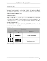
Page 21: ...the UPS cuts the power from its outlets and signals all malfunctions and their origins The emergency mode is signalled with a sound and blinking of the red LED in the load column as well as appropriate combinations of lit LEDs in the battery charge column see Table 1 The UPS remains in emergency mode until switched off by the user or until the batteries are completely discharged Table 1 Error tabl...

Page 22: ...e This is signalled by by the UPS by rapid blinking of the last LED red in the load indication column and a quick intermittent sound signal If the shorting lasts longer than 1 second the UPS will switch to the emergency operation mode Against overvoltage The UPS is equipped with anti overvoltage safeguard at the input which protects the circuits of receivers and the internal circuits of the UPS ag...

Page 23: ...nix and Novell systems only the RS232 communication is available INSTALLATION AND CONFIGURATION OF THE POWERSOFT PERSONAL SOFTWARE Installation on computers with Windows Prior to beginning the installation of PowerSoft Uninstall the current version of PowerSoft or any other control software in situations where the user is changing the UPS protecting the computer If the installed UPS communicates w...

Page 24: ...he UPS Update the device s driver from it s Properties window by right clicking it in the list and following the instructions onscreen As the driver s location you should indicate the PowerSoft installation folder usually C Program Files PowerSoft To uninstall PowerSoft select the Uninstall PowerSoft option in Start Menu You can also uninstall PowerSoft from the Add and remove programs menu in the...

Page 25: ...e following command pkg_delete PowerSoft WARNING FreeBSD systems do not support communication with the UPS via the USB cable Starting the software When the installation is complete the system service is started automatically while the control panel application can be found at usr local PowerSoft Please note that for the Polish diacritics to be correctly displayed the system locale should be Polish...

Page 26: ...e UPS can be upgraded with the EVER SNMP HTTP networkmanagement card It is a device that integrates the UPS with an Ethernet network The network adapter is located in a special slot located on the rear panel of the UPS With the network adapter installed the user can control the UPS from any computer connected to the network This solution is most frequently used in cases of central power supply or ...

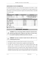
Page 27: ...R 195 205 V 200 V MAINS BAT 250 280 V 265 V BAT MAINS 245 275 V 260 V BAT battery operation mode MAINS mains operation mode MAINS AVR mains operation mode with AVR system engaged ADDITIONAL REMARKS CAUTION This is a C2 category UPS In domestic environment the product may interfere with reception of radio waves so the user may be required to implement additional preventive measures WARNING No servi...

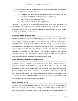
Page 28: ... 50Hz When connected to a power generator the frequency variations change over time and are strictly dependent on changes of load levels If the frequency variations of a power generator s voltage exceed the allowed tolerance range the UPS will consider such frequency to be incorect and switch to battery operation mode USING THE TELECOMMUNICATIONS FILTER In order to protect the telephone line and c...

Page 29: ...riginal or incomplete packaging is used EVER Sp z o o shall not be liable for any mechanical damages that occur in transport DISPOSAL Appropriate disposal of used up electric and electronic equipment helps to avoid consequences resulting from the presence of dangerous materials as well as inappropriate disposal and processing of such equipment which may be hazardous to human life and the environme...

Page 30: ...h internal batteries only 100 80 50 Pmax 7 8 5 19 min 5 7 15 min 4 5 9 min Support time with battery module installed 100 80 50 Pmax 28 48 81 min 25 34 65 min 17 24 46 min Battery 4x VRLA 12V 9 Ah Additional modules 2x 4x VRLA 12V 9 Ah Maximum charging time of internal batteries 6 3 h Maximum charging time of internal batteries battery module 6 12 h MECHANICAL PARAMETERS Dimensions h x w x d 190 1...

Page 31: ...Support time with internal batteries only 100 80 50 Pmax 7 8 5 19 min 5 7 15 min 4 5 9 min Support time with battery module installed 100 80 50 Pmax 28 48 81 min 25 34 65 min 17 24 46 min Battery 4x VRLA 12V 9 Ah Additional modules 2x 4x VRLA 12V 9 Ah Maximum charging time of internal batteries 6 3 h Maximum charging time of internal batteries battery module 6 12 h MECHANICAL PARAMETERS Dimensions...

Page 32: ...ith such defects The manufacturer shall make the decision as to how the defect is removed The warranty shall not cover devices with mechanical damages that occurred as a result of negligence of incorrect use nor devices subjected to any modifications made by the user Apart from the arrangements included in the warranty card EVER Sp z o o shall not grant any guarantee or warranty including warranty...

Reviews: