SINLINE XL series UPS – Instruction Manual
2010/01/27
www.ever.eu
6
The right column of green LEDs indicates the percentage load
level of the UPS in both the mains and battery operation
mode. If the top LED is lit in red and the UPS is emitting
a continous sound signal, this indicates that the UPS has
overloaded. However, if the red LED is blinking and the UPS
is emitting a quick intermittent signal, this indicates a shorting
at the back-up's output.If the UPS malfunctions, it switches off
automatically. The reason for shutdown is indicated by the
combination of LEDs lit (see "Description of the UPS’S
OPERATION").
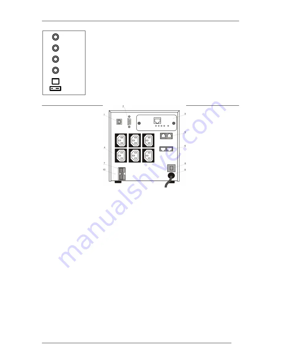
REAR PANEL
Fig. 2: Rear panel
1. USB port for communication with a PC
2. RS232 serial port for communication with a PC
3. Internal slot for an upgrade card (the figure above presents a UPS with a card
installed – it is an optional component)
4. Outlet sockets
5. Telecommunications filter
6. LAN filter
7. Socket for connecting an external battery module
8. Mains circuit breaker
After the circuit breaker is triggered, the reason for shorting should be
removed and the breaker pressed back in to be activated.
9. Mains power cord
10.
Stopper for the external battery module socket.
>5%
>30%
>60%
>85%
Summary of Contents for SINLINE XL 1800
Page 1: ......


